Materials
Materials control how surfaces look in your renders—their color, reflectivity, transparency, and texture. Every SketchUp material in your model has a corresponding Rayscaper material with the same name, but Rayscaper materials offer many more options for creating realistic visualizations.
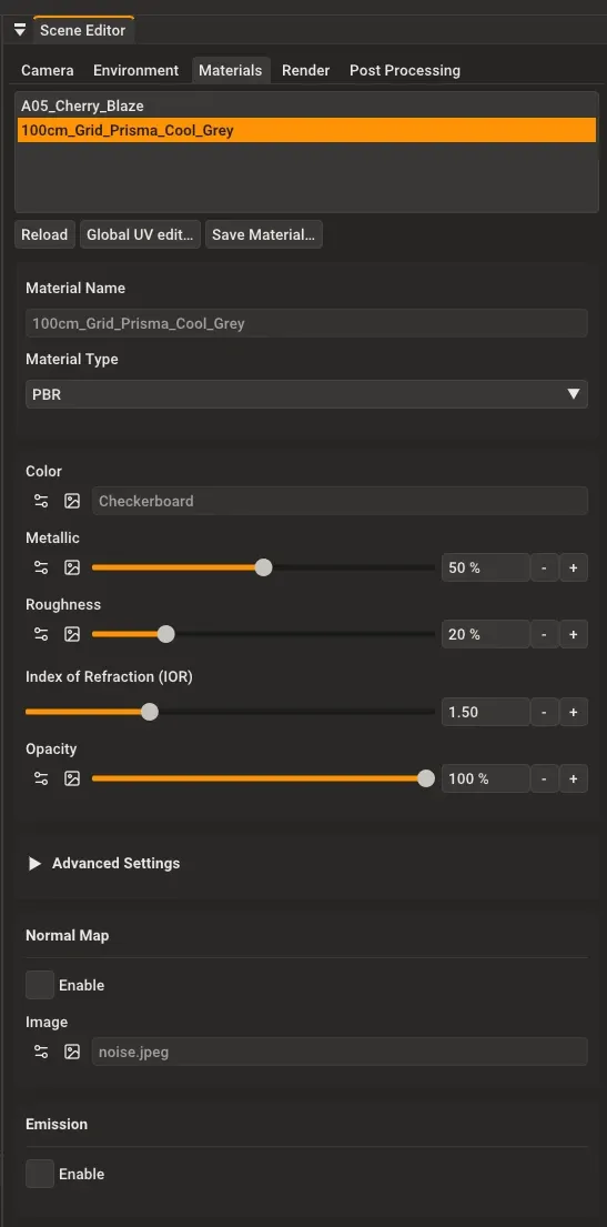
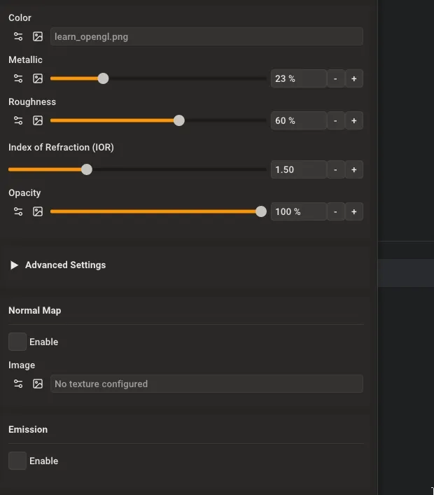
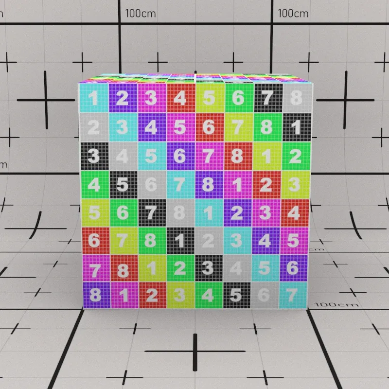
The Rayscaper materials panel: select a material from the list (top) to edit its properties (bottom).
Working with SketchUp Materials
Section titled “Working with SketchUp Materials”Rayscaper automatically creates materials when you work in SketchUp. When you create a new SketchUp material, Rayscaper creates a matching material with the same color, texture, and opacity. This gives you a starting point to work from.
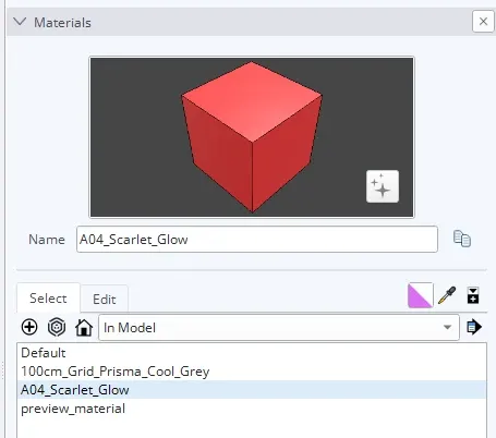
SketchUp materials panel with materials list. Each SketchUp material has a corresponding Rayscaper material.
After this initial sync, changes in SketchUp are not automatically applied to Rayscaper—this protects any customizations you’ve made. To manually update a Rayscaper material with the current SketchUp settings, use the Reload button. To clear all customizations and restore a material to its default settings, use the Reset button.
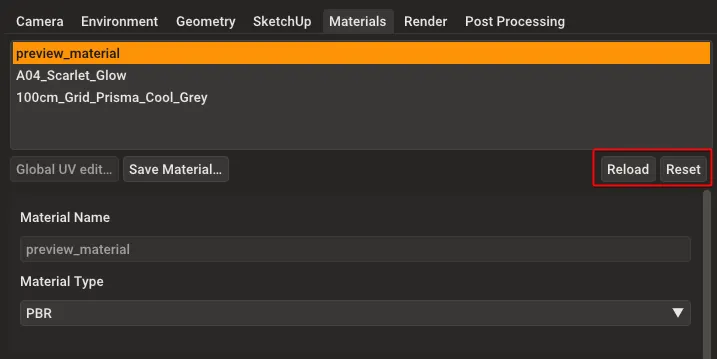
Click Reload to resync a material with its current SketchUp settings, or Reset to restore default material settings.
Renaming a material in SketchUp automatically renames the corresponding Rayscaper material.
Material Requirements
Section titled “Material Requirements”For Rayscaper to render your geometry correctly, every face in SketchUp must have a material applied to its front side.
In SketchUp, faces without an assigned material use the “default material” (shown as white or light gray in SketchUp). Rayscaper does not support this default material—faces must have an actual named material applied.
If a face has no material assigned, Rayscaper looks for one on the containing group or component. If no material is found anywhere in the hierarchy, the face renders in clay color—a matte beige appearance that indicates missing material assignments.
Textures
Section titled “Textures”Textures control how material properties vary across a surface. Instead of uniform red, you can use a wood grain image for the color. Instead of constant roughness, worn areas can be rougher than polished areas.
Every material property in Rayscaper uses a texture. The simplest texture is a constant—a solid color or fixed number. For more complex effects, use images, procedural patterns, or combinations.
Click the arrow icon next to any property to choose a texture type.
Each property has texture controls: click the arrow or icon to select a texture type.
Constant
Section titled “Constant”A constant texture is a single value—either a solid color or a fixed number. Color properties use a color picker, while single-value properties use sliders.
Click the color swatch to open the color picker and choose a color.
Drag sliders to adjust single-value properties like Metallic, Roughness, IOR, and Opacity.
Image textures use image files to control material properties. This is how you create realistic materials—using photographs or texture maps for color, roughness, and other properties.
Click the image icon next to a property to load an image file. The property shows the filename once loaded.
Once an image is loaded, you can adjust its settings. The image texture panel shows the loaded file, transformation controls, and rendering options.
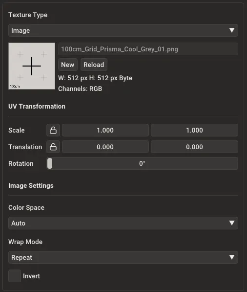
The image texture settings panel with all available options.
Loading Images
Section titled “Loading Images”The panel shows the currently loaded image file with its dimensions and color channels. Use the buttons to manage the image:
- New: Load a different image file from disk
- Reload: Refresh the image after editing it in an external program
UV Transformation
Section titled “UV Transformation”These controls adjust how the image is positioned and scaled on your surfaces:
- Scale: Make the image larger or smaller. Values greater than 1 shrink the image; values less than 1 enlarge it
- Translation: Slide the image horizontally (X) or vertically (Y) without rotating it
- Rotation: Turn the image around its center. Enter degrees (90, 180, etc.) or use the slider

Image Settings
Section titled “Image Settings”Color Space: Tells Rayscaper how to read the image file:
- Auto (default): Automatically detects the correct color space. Works for most images
- sRGB: Standard for photos and web images (PNG, JPEG). Choose this if colors look wrong
- Linear: For HDR images (EXR, HDR) and technical textures that store data rather than colors
Wrap Mode: Controls what happens at the edges of the image:
- Repeat (default): Tiles the image across the surface. Works best with seamless textures where edges match up
- Black: Shows black (or zero) outside the image boundaries. Useful for decals or masked textures
- Clamp: Stretches the edge pixels outward. Good for preventing dark borders on non-tiling images
Invert: Reverses the image colors. Useful when a texture map is backwards (like inverting a roughness map to get smoothness).

Global UV Editing
Section titled “Global UV Editing”When you need to adjust multiple image textures together, use the Global UV Edit tool. This is helpful when a material uses several related textures (like color, roughness, and normal maps) that all need the same transformation adjustments.
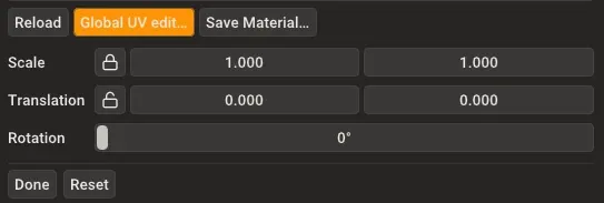
Global UV Edit mode showing transformation controls. Changes apply to all image textures in the material simultaneously.
While active, any transformation changes (Scale, Translation, Rotation) apply to all image textures in the material at once. Click Done to exit the tool, or Reset to revert changes.
Checkerboard
Section titled “Checkerboard”Creates an alternating checkerboard pattern without needing an image file. The pattern is generated procedurally at render time. Useful for test renders, UV layout verification, or creating geometric patterns.
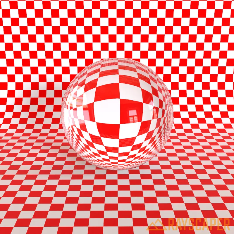
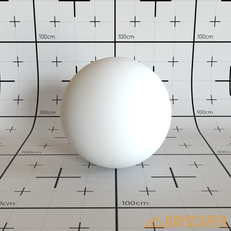
A glass sphere rendered on a checkerboard surface.
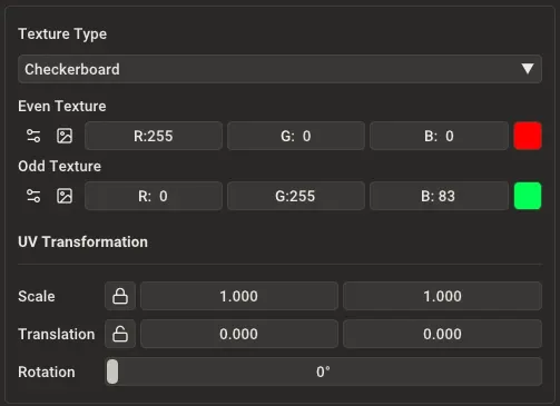
The Color property with Checkerboard texture selected, showing Even Texture (red), Odd Texture (green), and UV Transformation controls.
Even Texture: The texture for one set of squares. Use a solid color or any other texture type (image, noise, etc.).
Odd Texture: The texture for the other set of squares. Use a solid color or any other texture type (image, noise, etc.).
UV Transformation: Controls the size, position, and rotation of the checkerboard pattern:
- Scale: Values greater than 1 make the squares smaller; values less than 1 make them larger
- Translation: Shifts the pattern horizontally (X) or vertically (Y)
- Rotation: Rotates the entire pattern in degrees
Blends two textures together based on a blend amount. Useful for layering effects, combining materials, or creating transitions between textures.
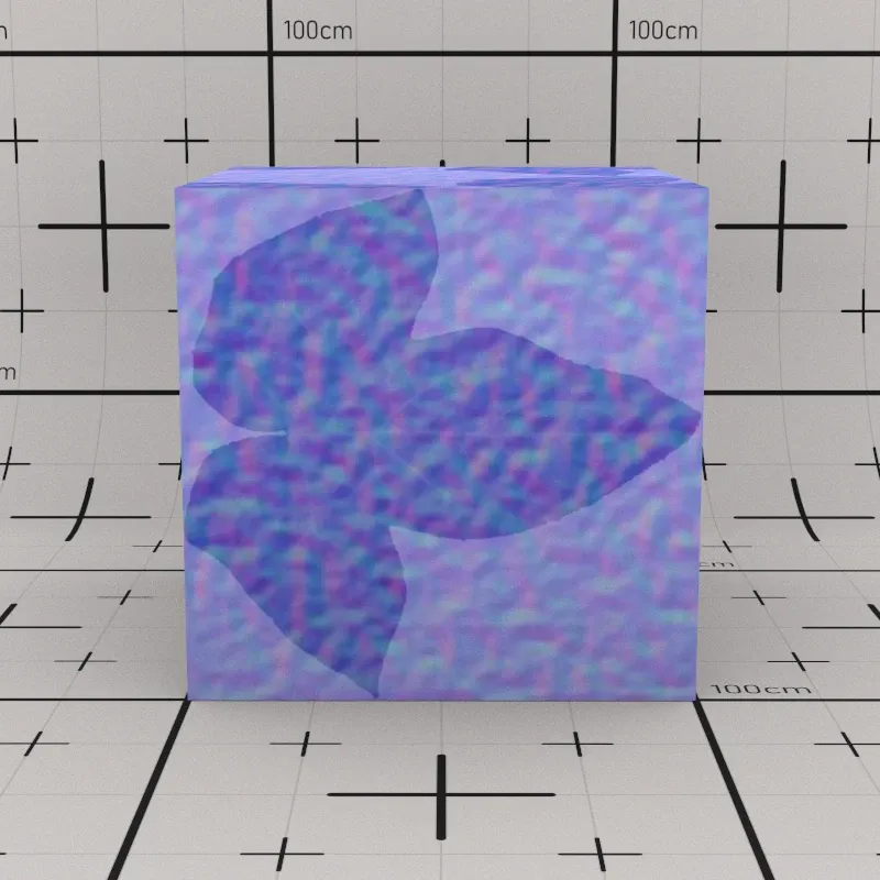
A leaf texture blended with procedural noise using Mix.
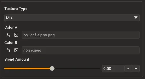
Mix texture controls showing two texture inputs and a blend slider.
Color A: The first texture. Click the texture controls to choose any texture type (constant, image, checkerboard, noise, or another mix).
Color B: The second texture. Click the texture controls to choose any texture type (constant, image, checkerboard, noise, or another mix).
Blend Amount: Controls the mix between the two textures. A value of 0% shows only Color A, 100% shows only Color B, and 50% blends them equally. You can also use a texture for the blend amount to create masks.
Creates organic, random patterns without using image files. The pattern is generated procedurally based on mathematical noise functions. Useful for adding natural variation, creating clouds, marble effects, or breaking up uniform surfaces.
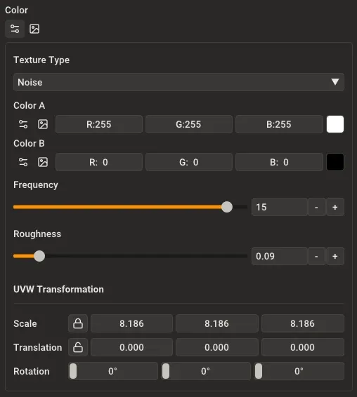
Noise texture controls with Color A (white), Color B (black), Frequency, Roughness, and UVW Transformation.
Color A: The color used in darker areas of the noise pattern. Click the texture controls to use a solid color or any other texture type.
Color B: The color used in lighter areas of the noise pattern. Click the texture controls to use a solid color or any other texture type.
Frequency: Controls the scale of the noise pattern. Low values (1-4) create large, smooth variations. High values (8-16) create fine, detailed noise. Think of it as zooming in or out of the pattern.
Roughness: Adds layers of fine detail on top of the base pattern. A value of 0% creates smooth, flowing noise. Higher values (50-100%) add more complexity and turbulence, similar to clouds or marble.
UVW Transformation: Unlike 2D textures that map to surfaces, noise exists in 3D space. These controls let you scale, translate, and rotate the noise pattern in three dimensions. This means the pattern stays consistent as you move through it, like carving a sculpture from a block of marble.
Common Material Settings
Section titled “Common Material Settings”All materials share these properties: Color, Opacity, Normal Map, and Emission. They work the same way regardless of material type.
Controls the base appearance of the material. Like other properties, Color uses a texture—choose between a solid color, an image texture (albedo or diffuse map), or procedural patterns like checkerboard or noise.
For realistic materials, use an image texture that shows the surface’s natural color. For simple materials, a solid color works well.
Opacity
Section titled “Opacity”Controls material transparency. 0% is fully transparent, 100% is fully opaque.
Normal Map
Section titled “Normal Map”Adds surface detail without extra geometry by changing how light interacts with the surface. Normal maps store surface directions in the RGB channels of an image—the dominant blue/purple color comes from the Z-direction data.
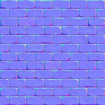
A brick normal map showing the characteristic blue/purple appearance with surface detail information.
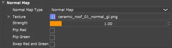
Normal map settings panel showing Enable, Image, Strength, Format controls.
Enable: Turn normal mapping on or off for this material.
Image: Load a normal map image file. Must be a tangent-space normal map (the standard type produced by texture tools).
Strength: Controls how pronounced the surface detail appears. Higher values create deeper bumps and grooves. Range: 0-5, where 0 disables the effect. Use 1.0 for standard detail, or 2.0-3.0 for pronounced effects.
Format: The normal map convention—OpenGL (Y+) or DirectX (Y-). OpenGL is most common. Switch to DirectX if bumps and grooves appear inverted.
Flip Red: Inverts the horizontal direction. Use if surface details appear backwards or mirrored.
Swap Red & Green: Swaps the horizontal and vertical channels. Use for normal maps created in different coordinate systems or if the texture appears rotated 90 degrees.
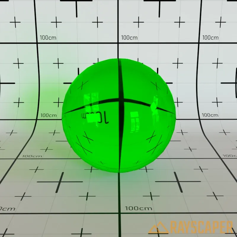
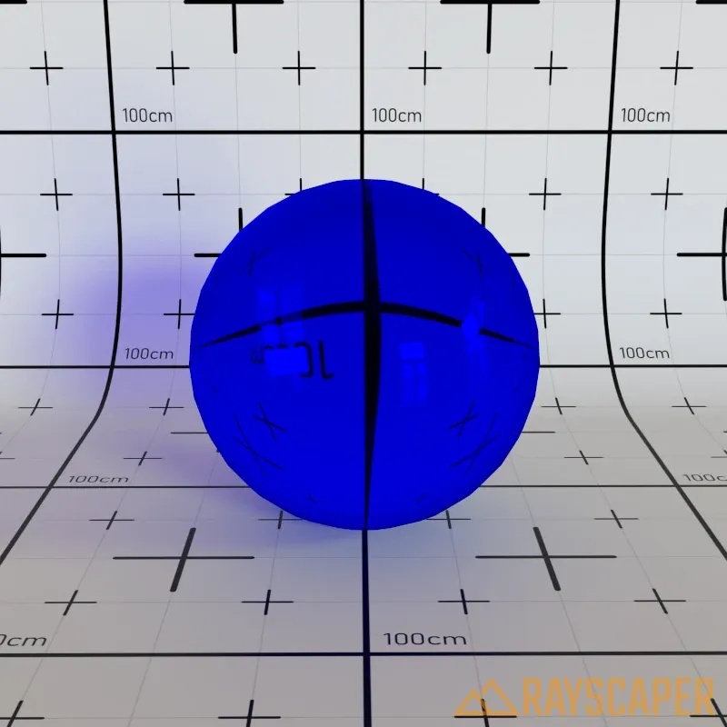
Emission
Section titled “Emission”Any material can emit light using one of two modes: Color or Temperature. By default, light is emitted from the front face only.

Emission controls showing Temperature mode with a gradient slider from warm (orange/red) to cool (blue).
Enable: Turn light emission on or off for this material.
Mode: Choose between Temperature (physically accurate blackbody radiation) or Color (specific hue). Click the desired mode to switch between them.
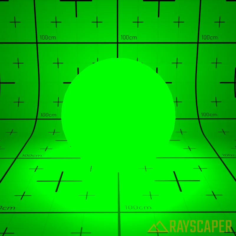
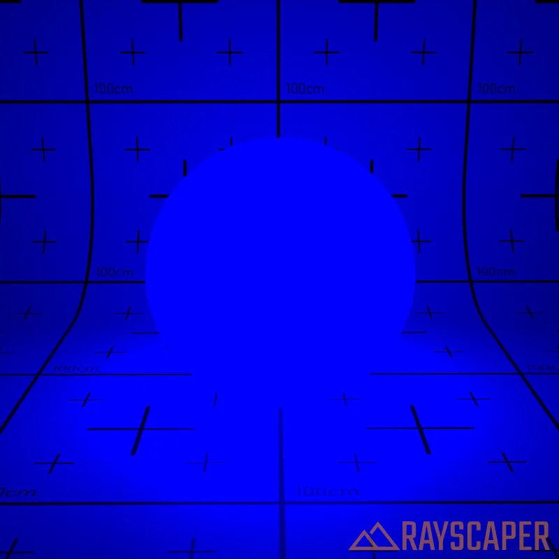
Temperature: Color temperature measured in Kelvin (K). The slider gradient shows how colors change from warm red/orange (1000-3000K) to cool blue/white (5000-10000K)—just like real light sources from candles to stars.
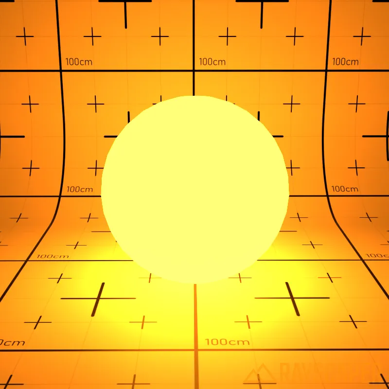
Power: Light intensity measured in watts. Higher values produce brighter light.
Two Sided: Emit light from both sides of the surface instead of just the front face.
Fake Emitter: Make the material appear bright without actually illuminating the scene. Useful for reducing render times when you want the look of glowing surfaces without the performance cost of real light emission.
Material Types
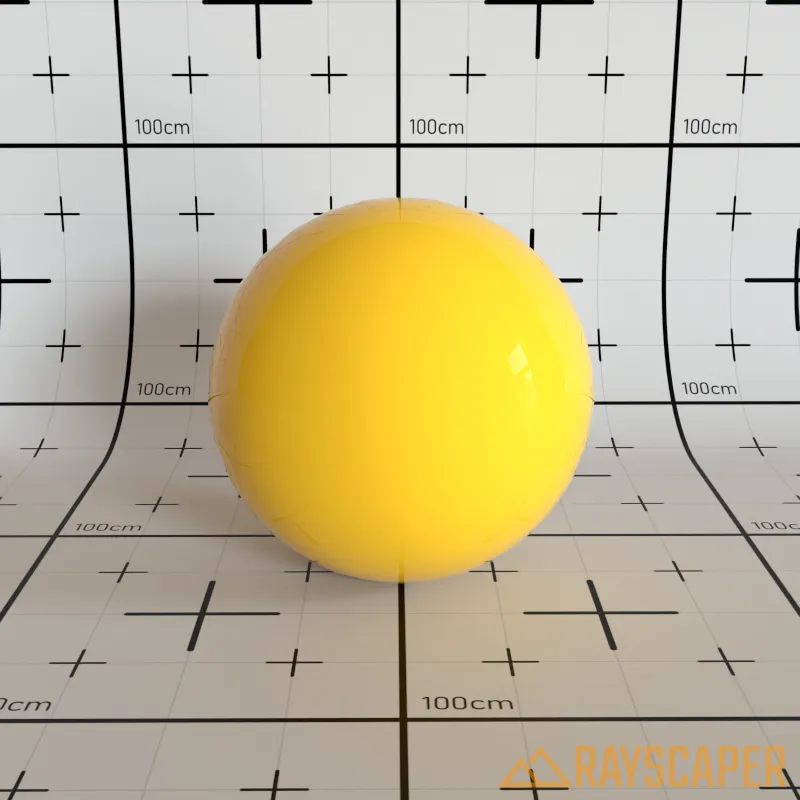
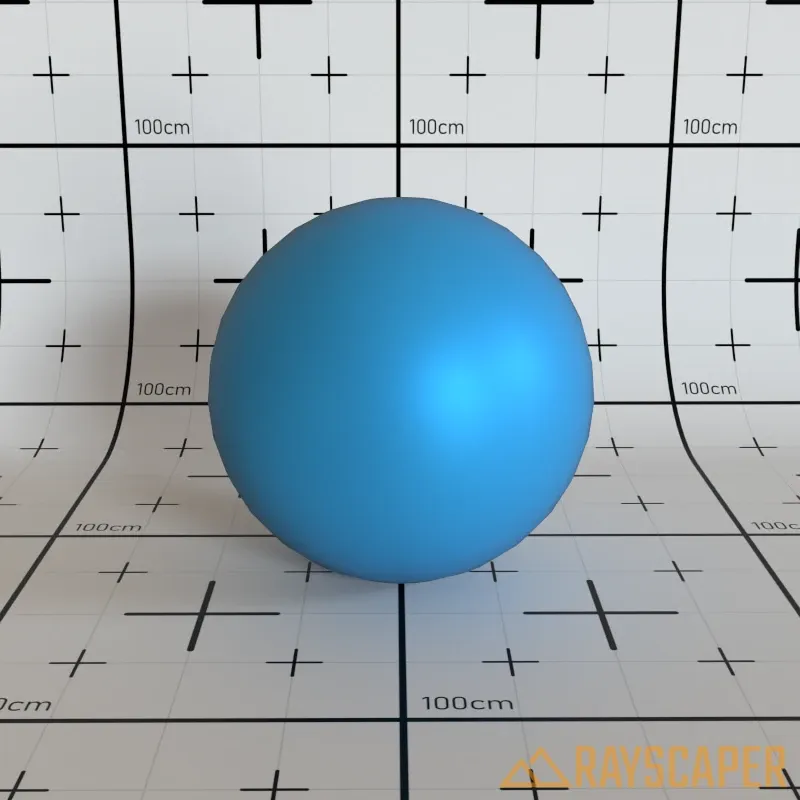
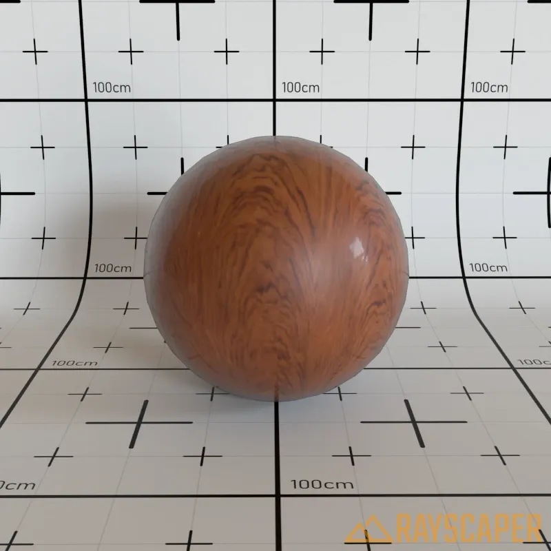
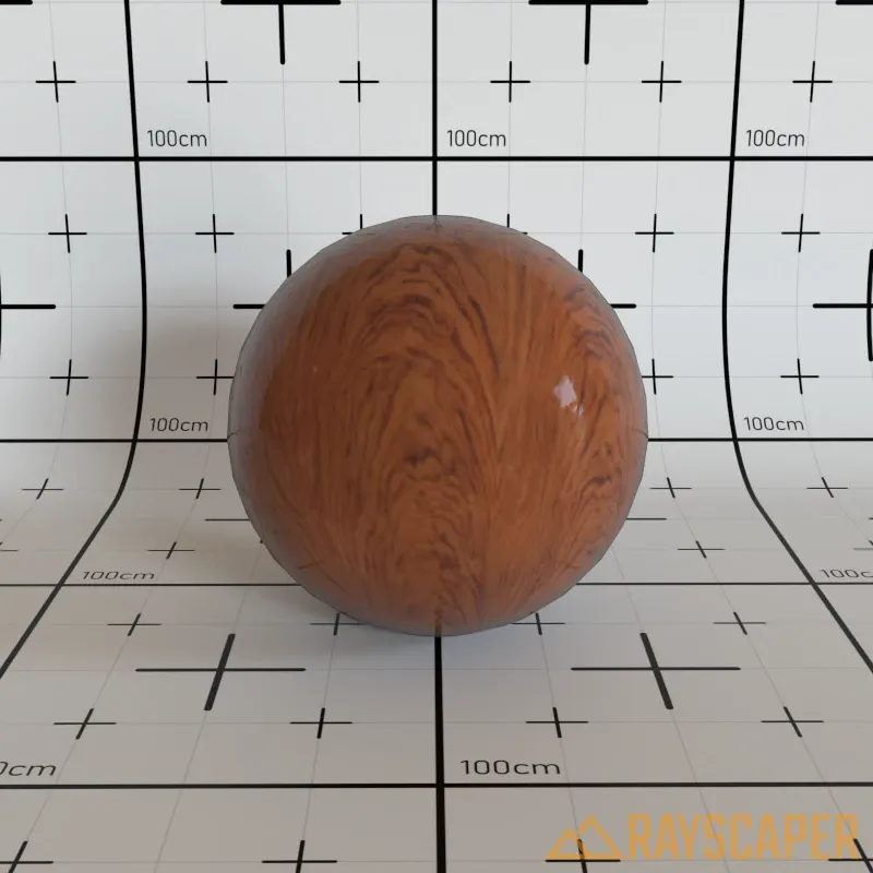
Section titled “Material Types”Coated Material
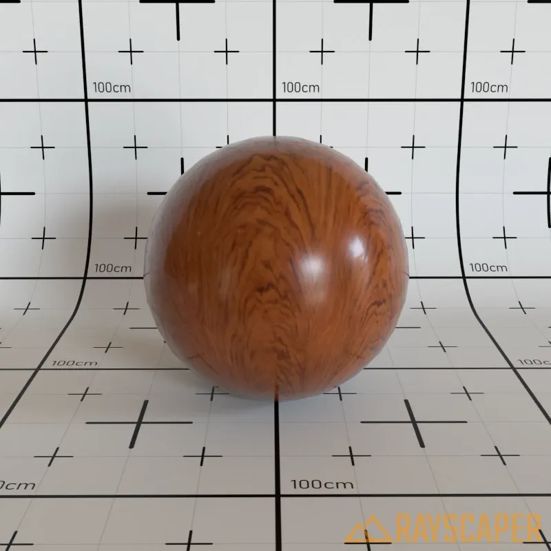
Section titled “Coated Material”A diffuse base with a glossy clear coat on top. Ideal for laminated flooring, car paint, varnished wood, and similar glossy-over-matte surfaces.
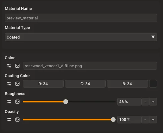
Coated material settings showing Color, Coating Color, Roughness, and Opacity controls.
Color: The base diffuse color or texture. Use a solid color or load an image texture for the underlying surface.
Coating Color: The tint of the glossy reflection layer. Controls the color of the clear coat reflections.
Roughness: Controls the sharpness of the coating reflections. A value of 0% produces mirror-like reflections, while higher values create increasingly blurred reflections.
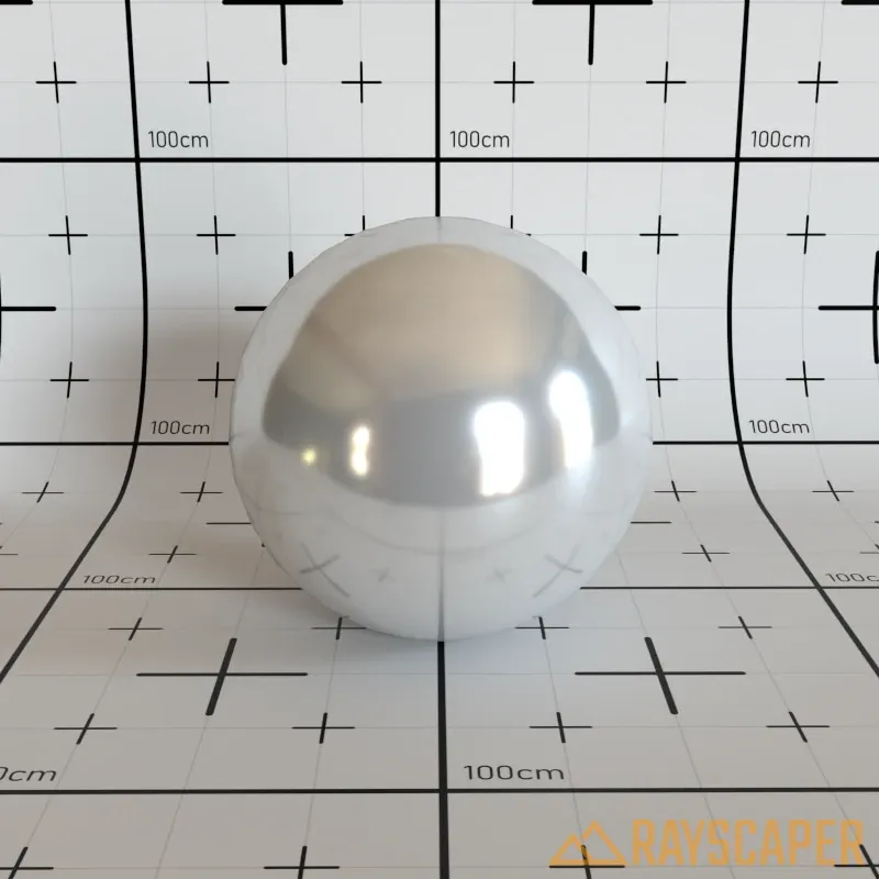
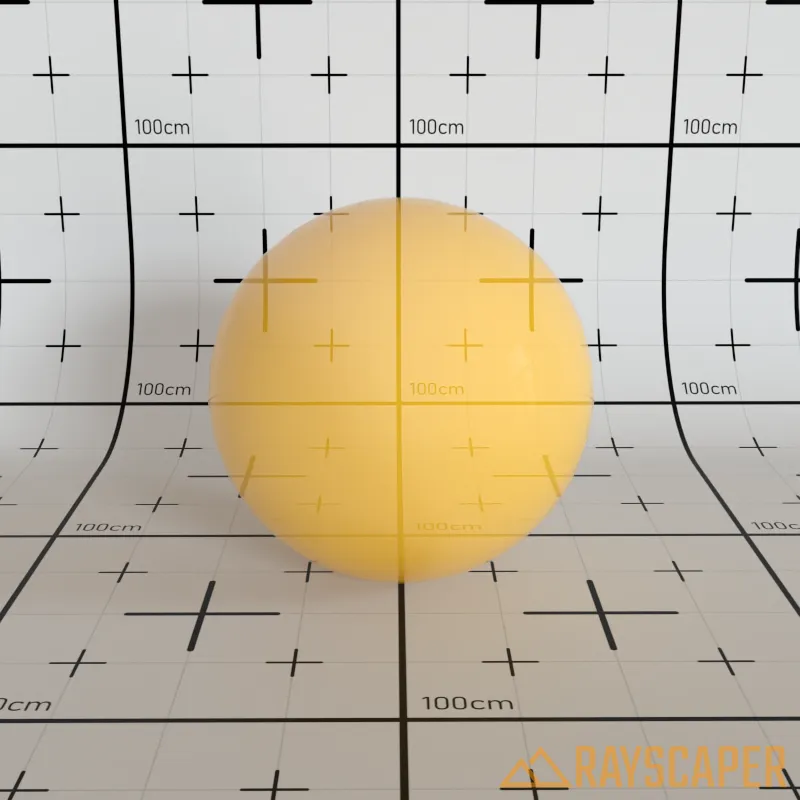
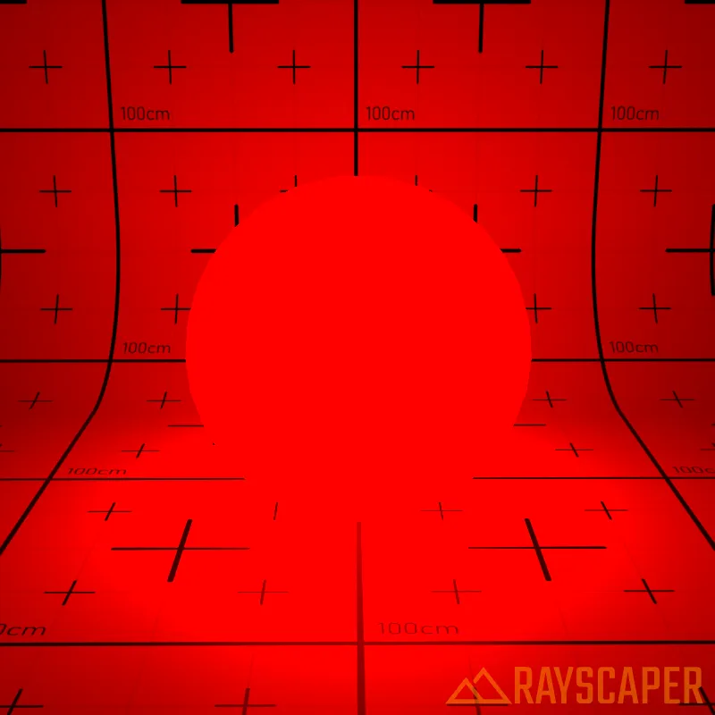
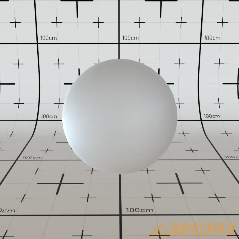
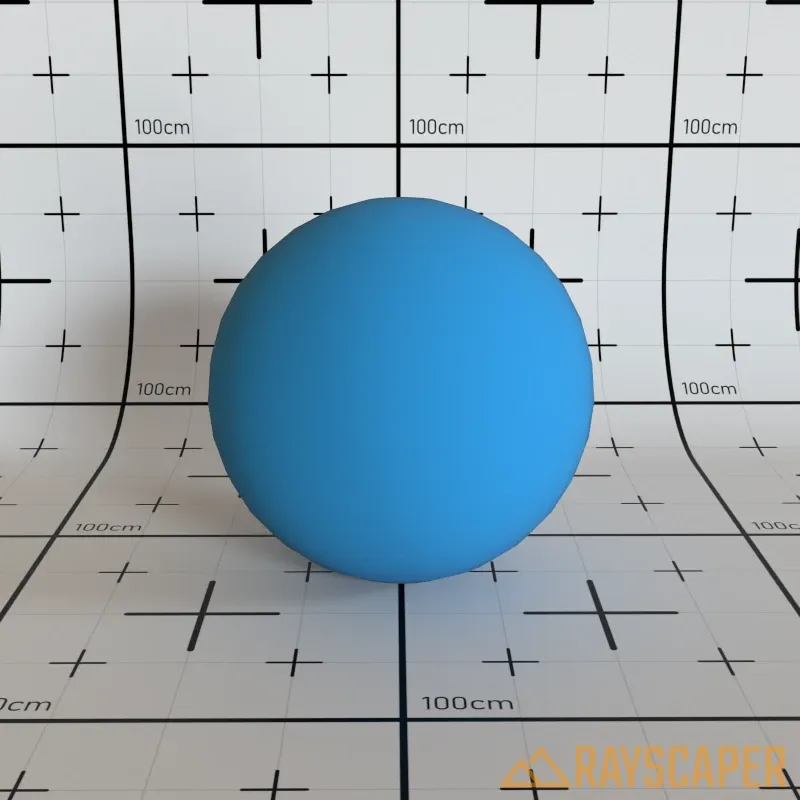
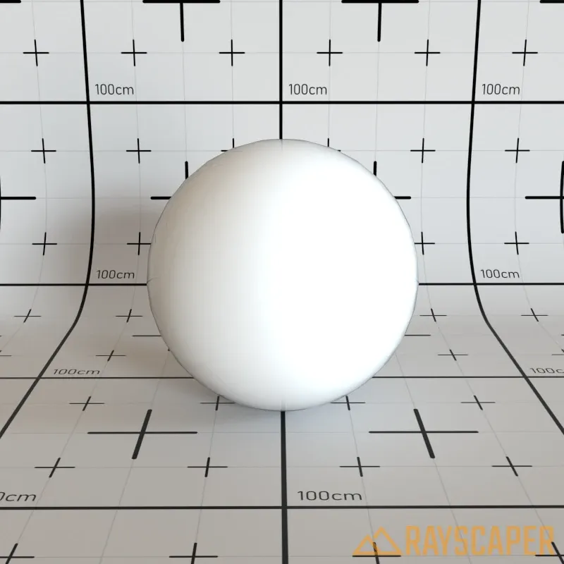
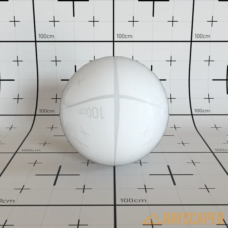
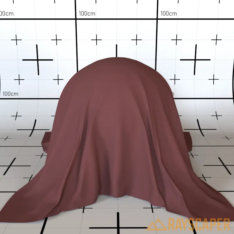
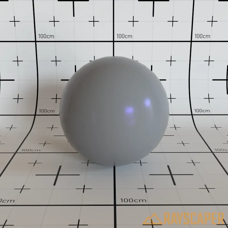
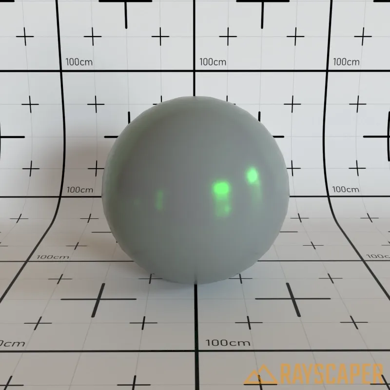
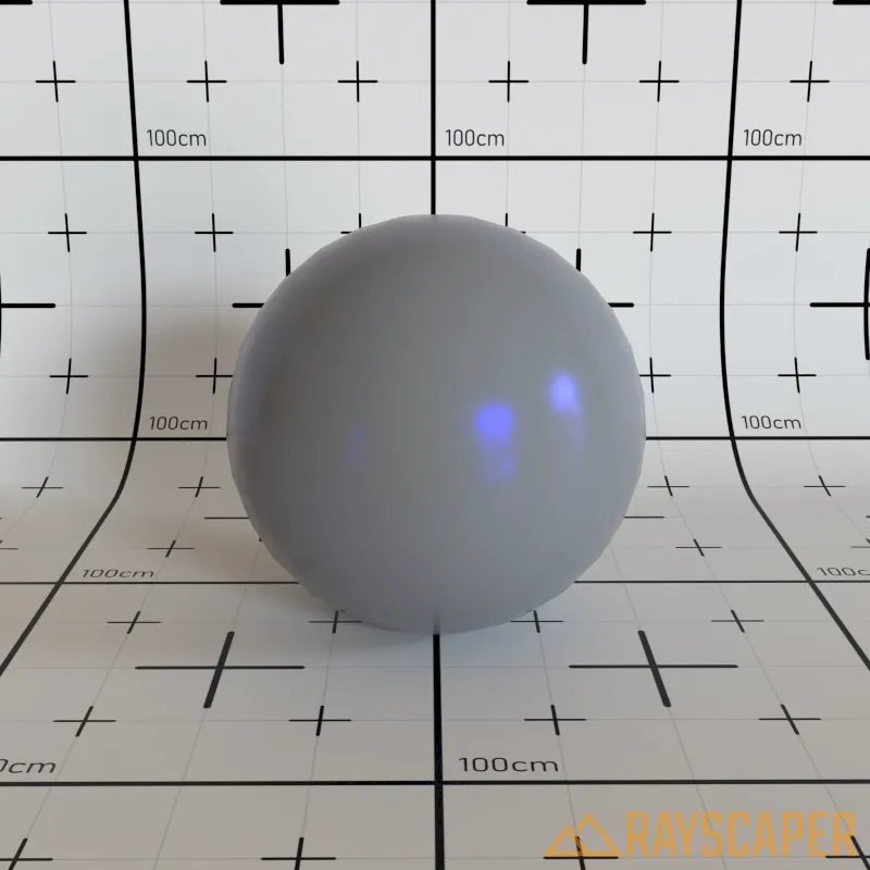
Diffuse Material
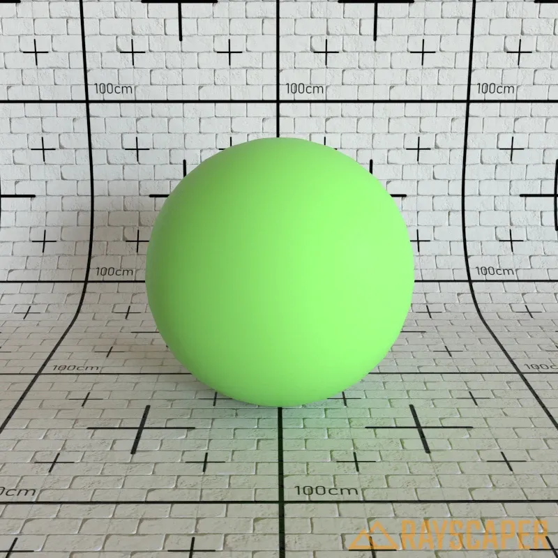
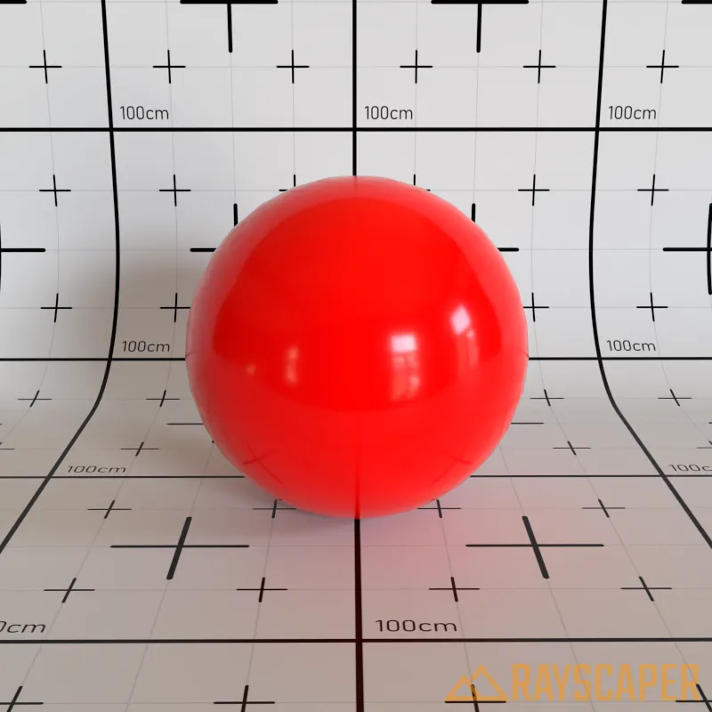
Section titled “Diffuse Material”The simplest material—a pure matte surface that scatters light equally in all directions. No additional settings beyond the common properties.
Diffuse material settings showing Color and Opacity controls.
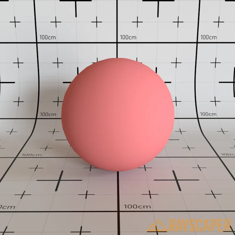
A red diffuse material with no reflections or transparency—just pure matte color.
Color: The surface color or texture. Use a solid color for simple materials, or load an image texture (albedo/diffuse map) for realistic results.
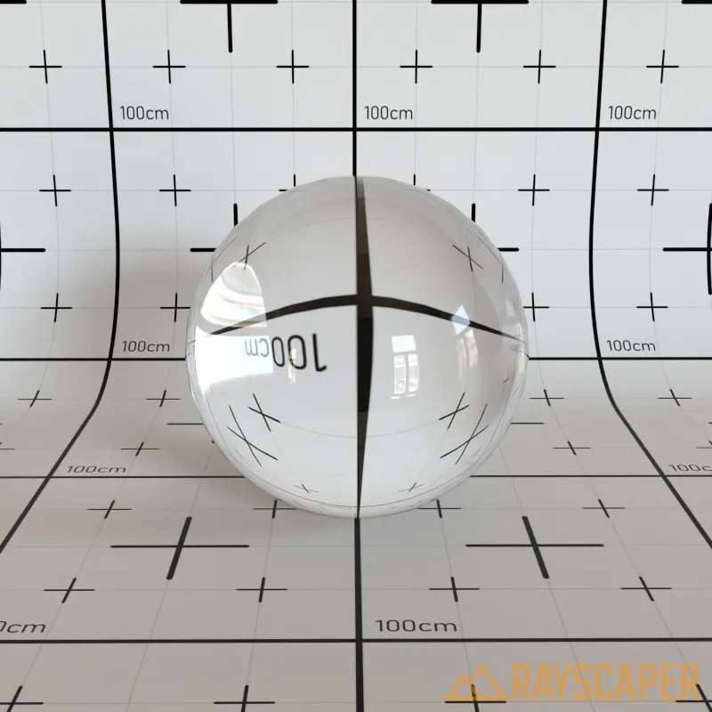
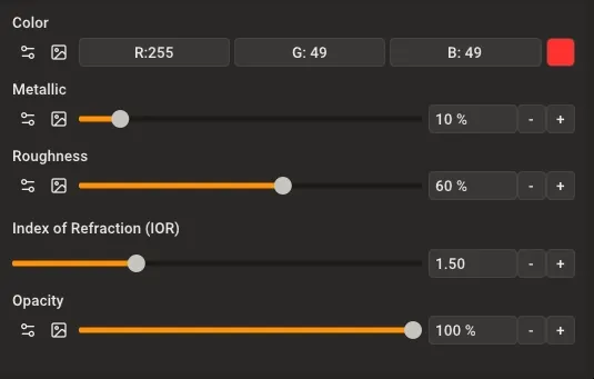
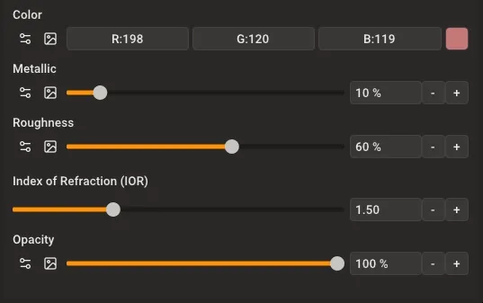
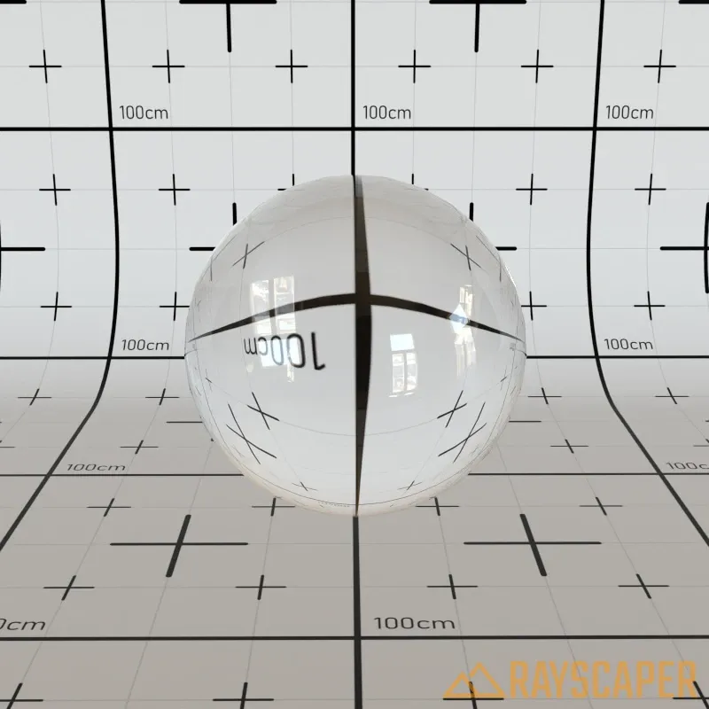
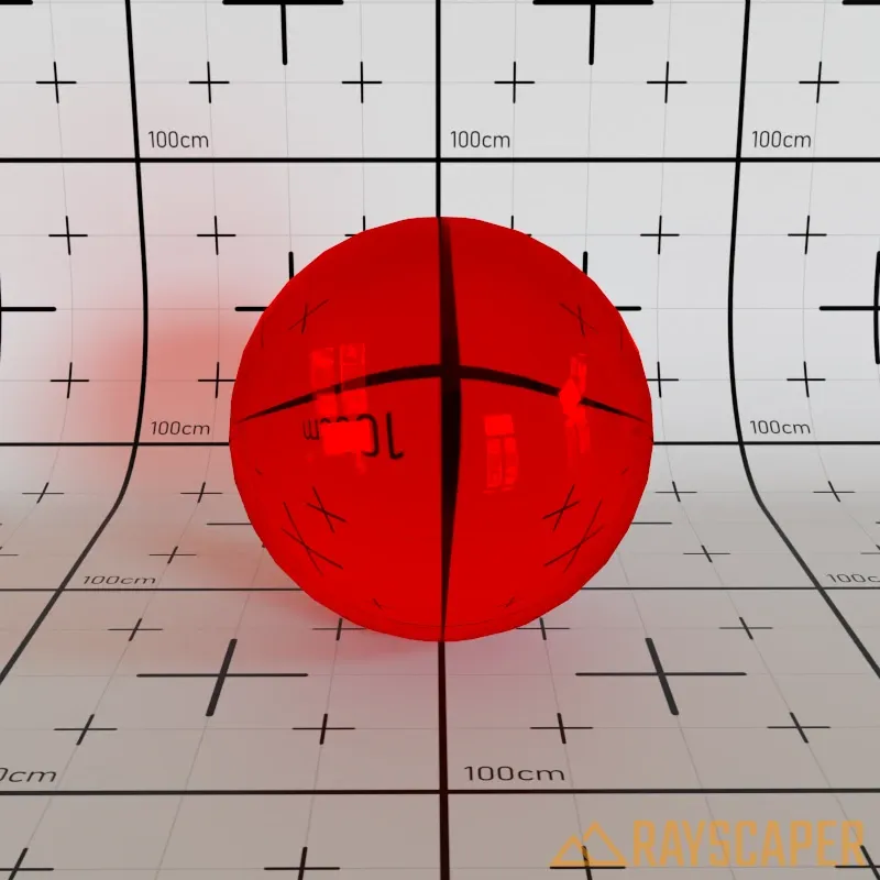
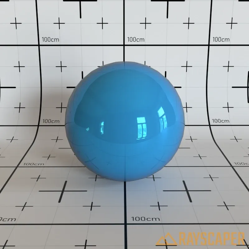
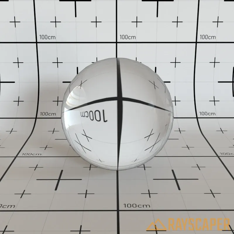
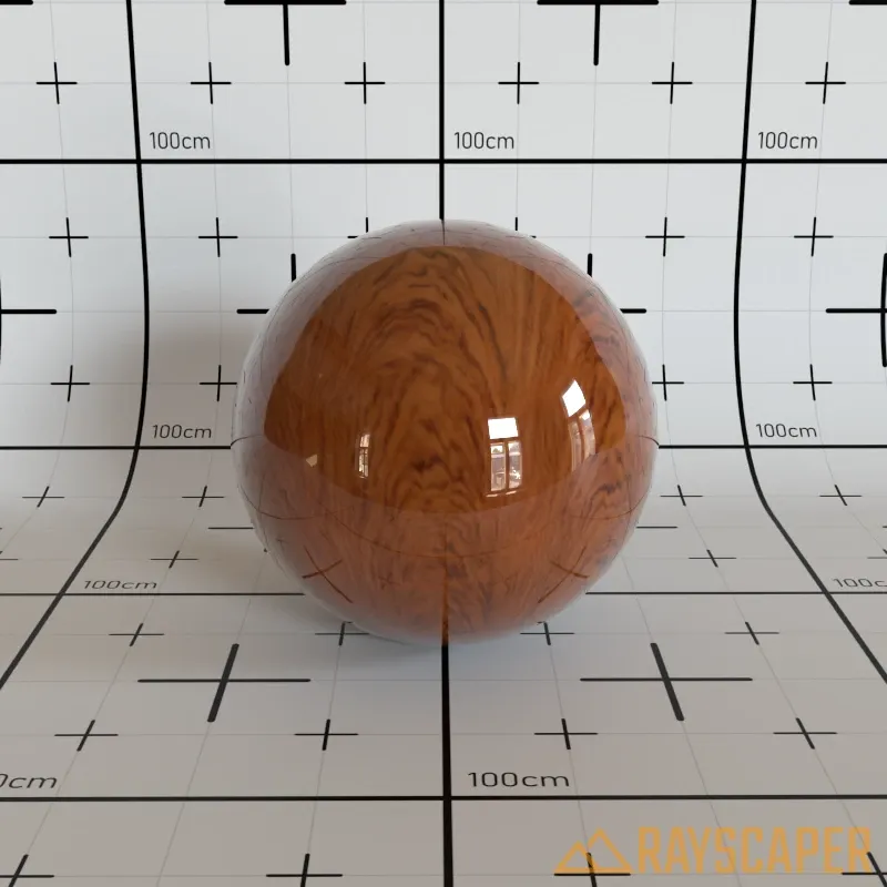
Glass Material
Section titled “Glass Material”Use this material for windows, drinking glasses, bottles, water, gemstones, and any transparent surface. Glass materials refract and reflect light just like real glass.
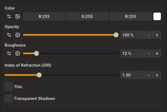
Glass material settings showing Color, Opacity, Roughness, IOR, Thin, and Transparent Shadows controls.
Color: Controls the glass tint. Keep this white for clear glass. Choose a color to create colored glass—the color affects both what passes through and what reflects off the surface.
Roughness: Makes glass look frosted or etched. Use 0% for clear glass like windows or drinking glasses. Increase this value to create privacy glass, shower doors, or decorative frosted glass.

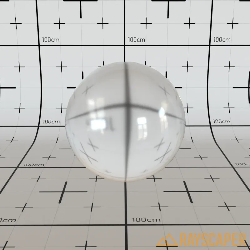
Index of Refraction (IOR): Controls how much light bends when passing through the glass, affecting how distorted objects appear behind it. Higher values create stronger distortion effects. Use the table below to find realistic values for different materials.
| Material | IOR Value |
|---|---|
| Air | 1.0 |
| Ice | 1.31 |
| Water | 1.33 |
| Glass | 1.5–1.7 |
| Ruby | 1.77 |
| Sapphire | 1.77 |
| Crystal | 2.0 |
| Diamond | 2.42 |
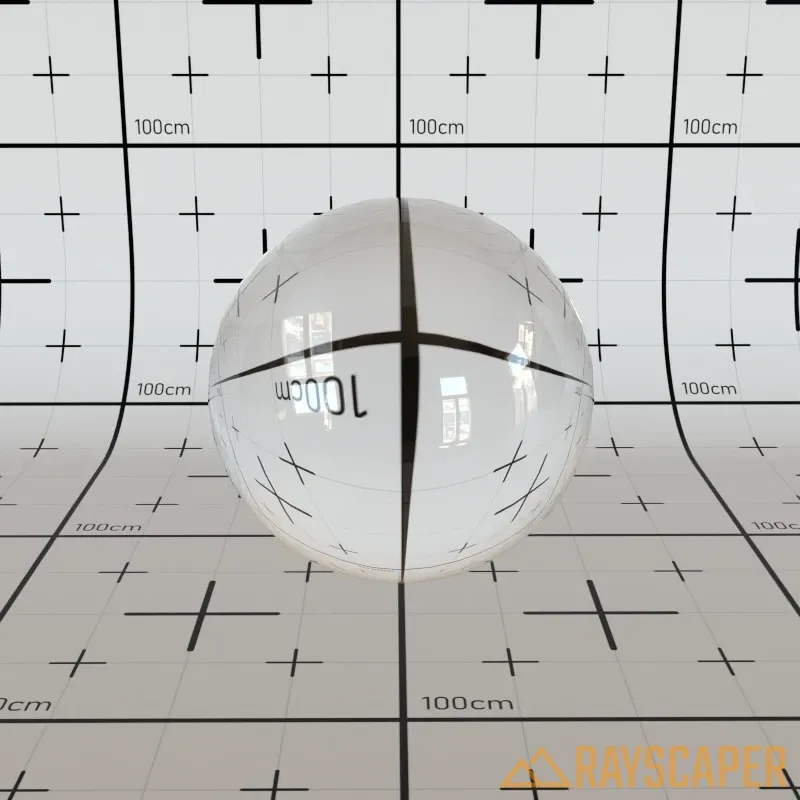
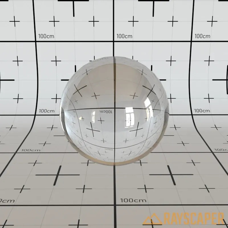
Thin: Use this for flat window panes in buildings. When enabled, Rayscaper treats the glass as having no thickness, which is faster to render and looks correct for architectural windows. Keep this off for objects with actual glass thickness like bottles, drinking glasses, or aquariums.

Transparent Shadows: Turn this on for windows in buildings. It allows sunlight to pass through the glass into interior spaces instead of casting dark shadows. Essential for architectural visualization—without it, rooms behind windows will be too dark.


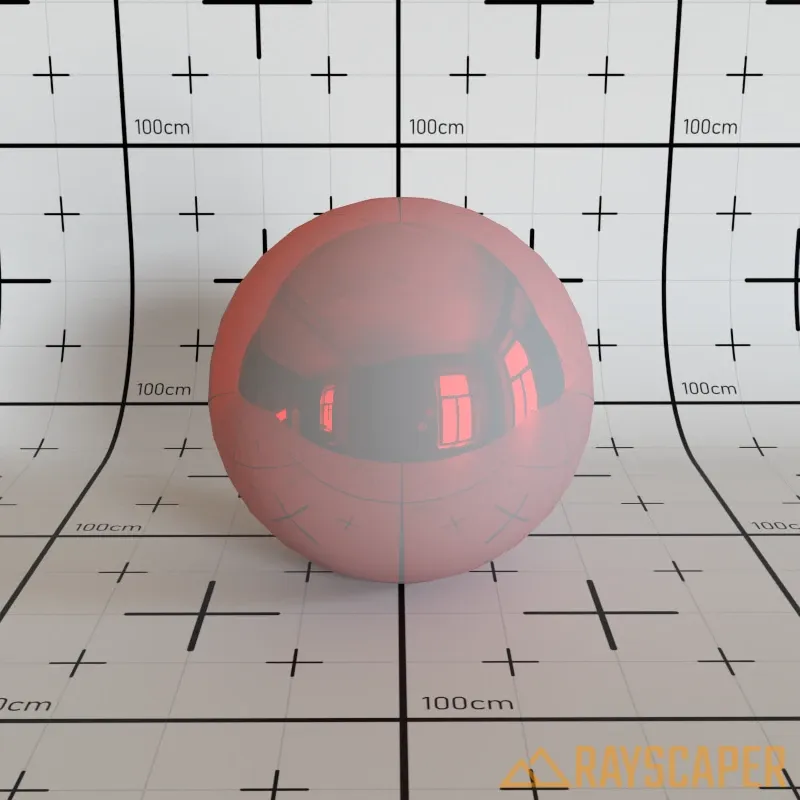
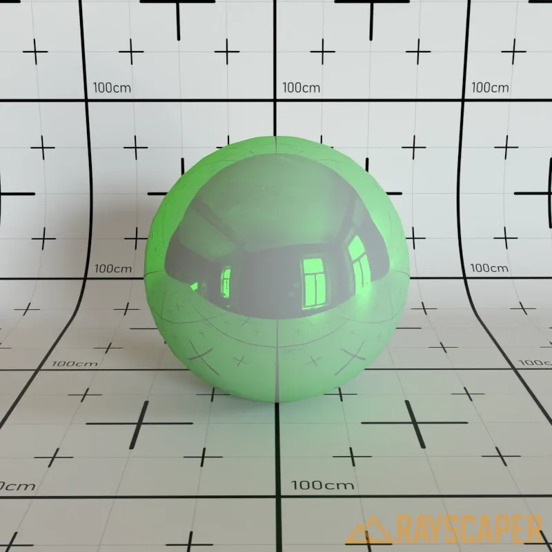
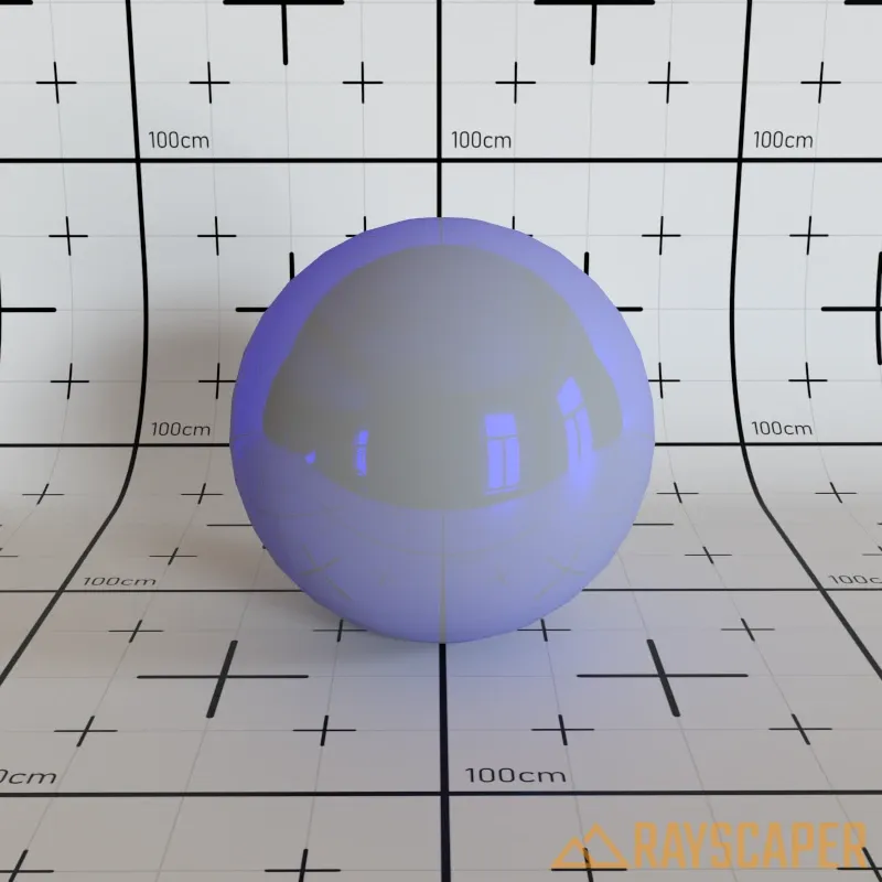
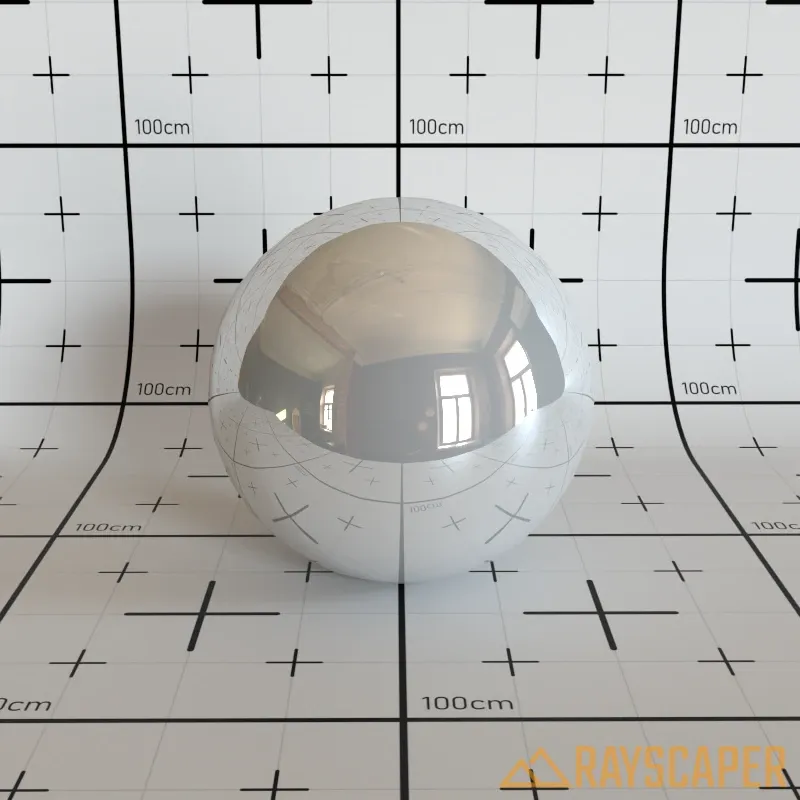
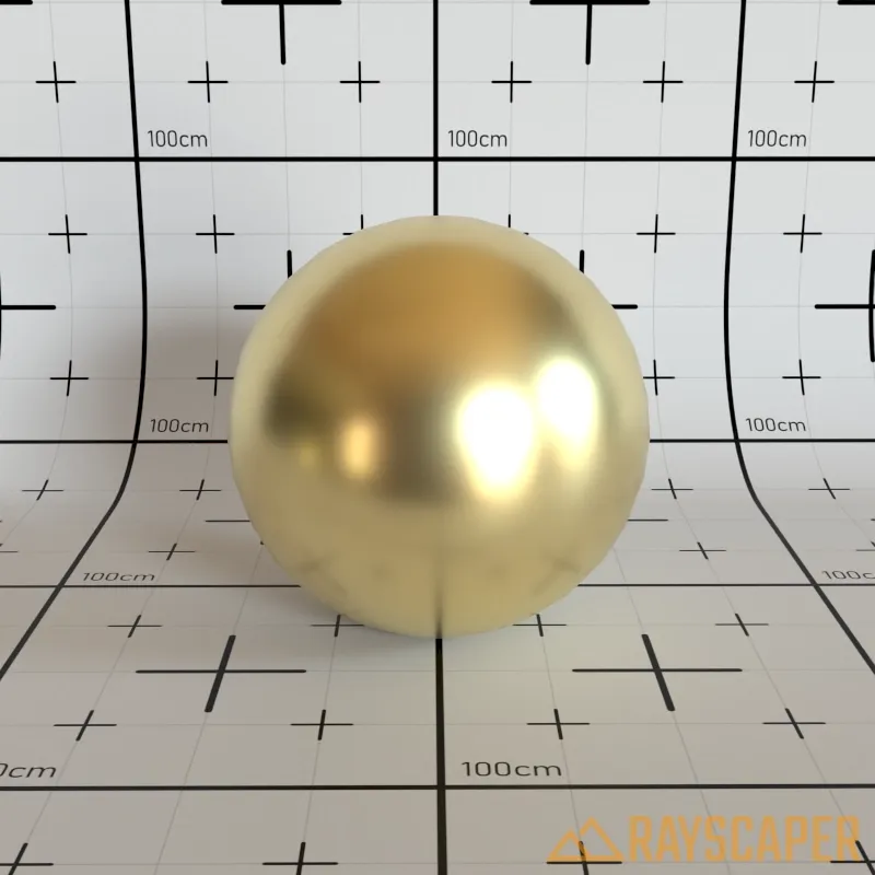
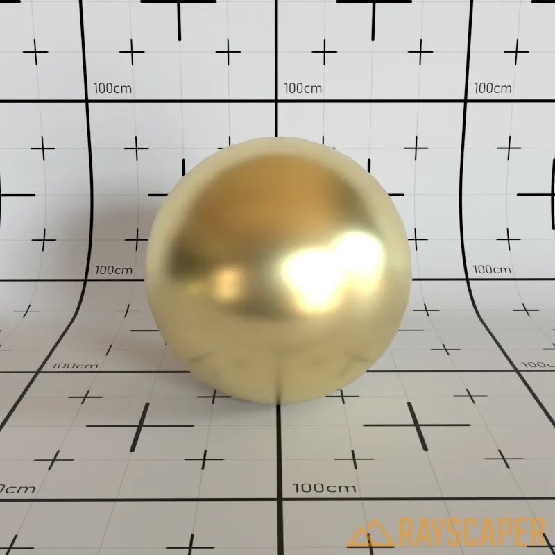
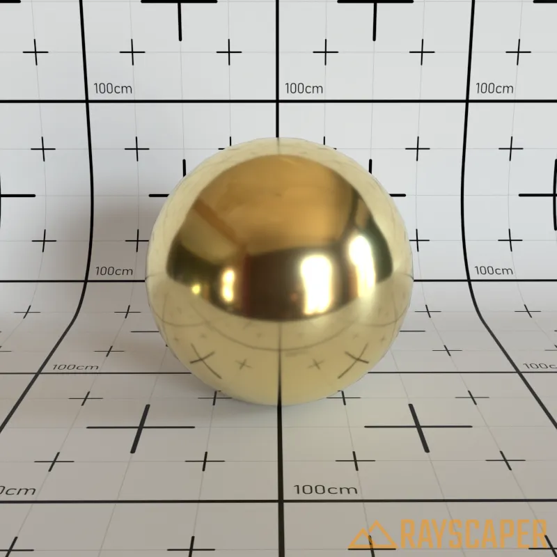
Metal Material
Section titled “Metal Material”Physically accurate metallic surfaces. Different metals have unique optical properties defined by their metallic IOR and absorption coefficients.
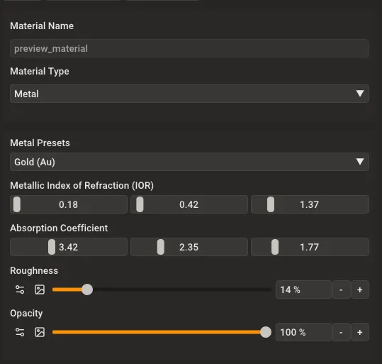
Metal material settings showing Metal Presets, Metallic IOR, Absorption Coefficient, Roughness, and Opacity.
Metal Presets: Choose from common metals with physically accurate optical properties. Selecting a preset automatically sets the Metallic IOR and Absorption Coefficient values for that metal.
Metallic Index of Refraction (IOR): The index of refraction for the metal, defined as RGB values. Each channel controls how the metal reflects different wavelengths of light.
Absorption Coefficient: Controls how the metal absorbs different wavelengths of light, defined as RGB values. Higher values mean more absorption, affecting the metal’s color and appearance.
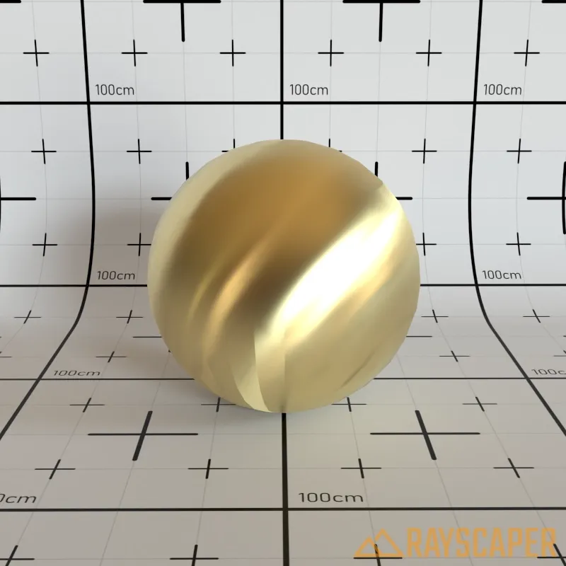
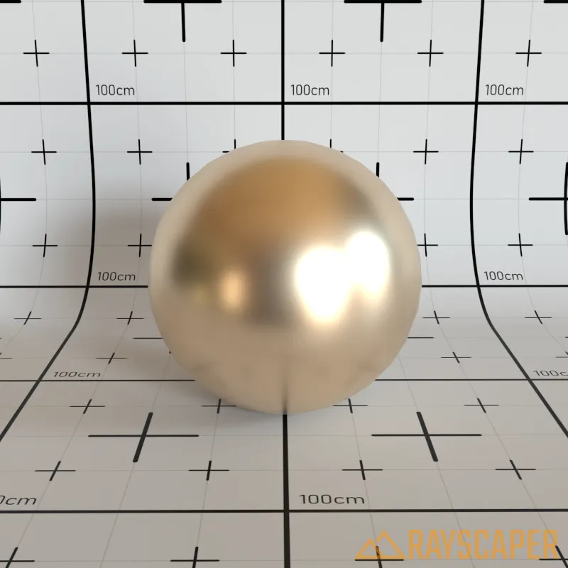
Roughness: Controls surface smoothness. A value of 0% produces mirror-polished metal, while higher values create brushed or weathered metal appearances.
Anisotropy: Controls the amount of anisotropy for specular highlights. Higher values elongate the highlights along the tangent direction. Use this to create brushed metal effects.
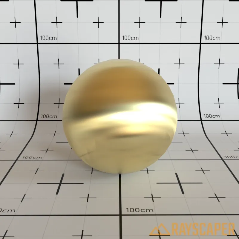
Anisotropy Rotation: Rotates the direction of the anisotropic highlight stretching in degrees (0-360°).


Reference values for common metals:
| Metal | Metallic IOR | Absorption Coefficient |
|---|---|---|
| Aluminium (Al) | (1.35, 0.97, 0.62) | (7.47, 6.40, 5.30) |
| Brass (Cu-Zn) | (0.44, 0.53, 1.09) | (3.70, 2.77, 1.83) |
| Copper (Cu) | (0.27, 0.68, 1.32) | (3.61, 2.62, 2.29) |
| Gold (Au) | (0.18, 0.42, 1.37) | (3.42, 2.35, 1.77) |
| Iron (Fe) | (2.91, 2.95, 2.58) | (3.09, 2.93, 2.77) |
| Nickel (Ni) | (1.99, 1.92, 1.73) | (4.21, 3.62, 2.94) |
| Platinum (Pt) | (2.38, 2.08, 1.85) | (4.27, 3.72, 3.14) |
| Silver (Ag) | (0.16, 0.15, 0.14) | (3.93, 3.19, 2.38) |
| Titanium (Ti) | (2.74, 2.54, 2.27) | (3.81, 3.43, 3.04) |
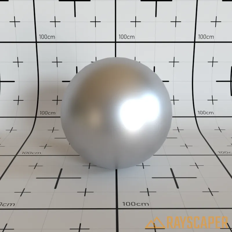
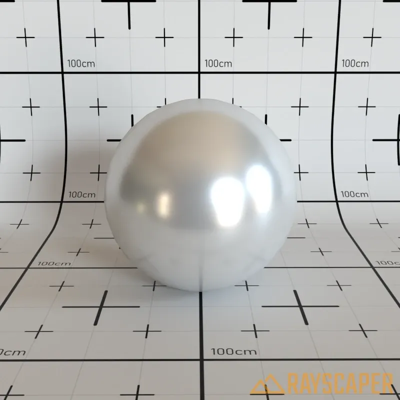
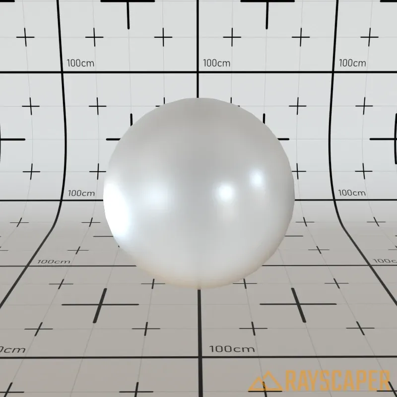
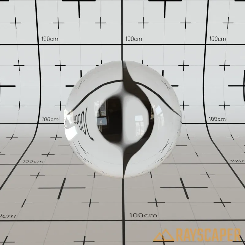
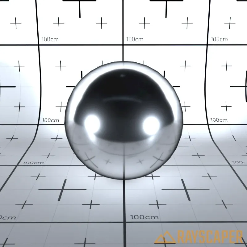
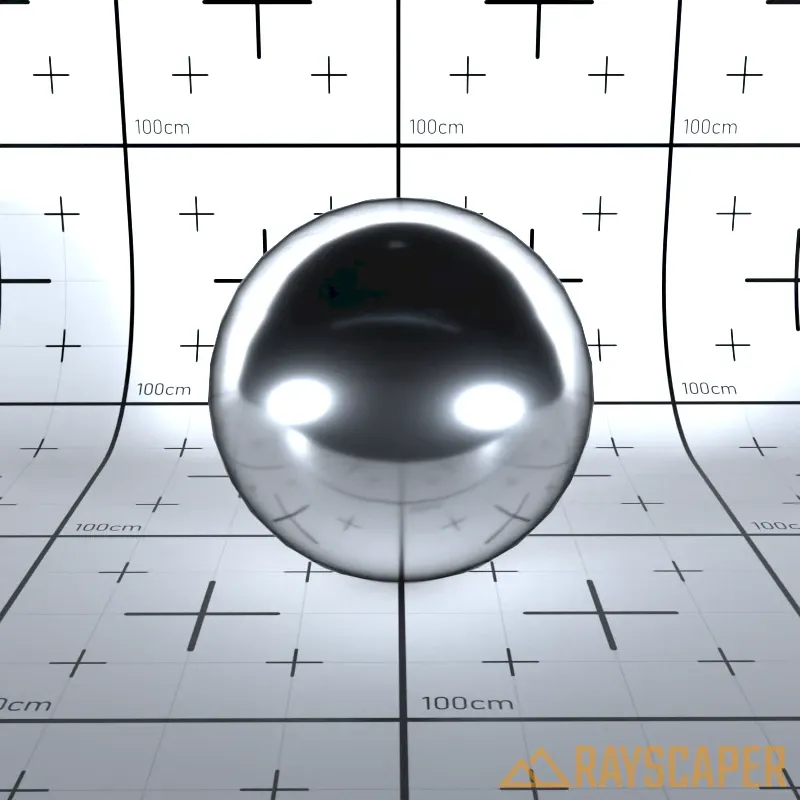
Mirror Material
Section titled “Mirror Material”A perfectly smooth, reflective surface. The Color property tints the reflection.
Mirror material settings showing Color and Opacity controls.
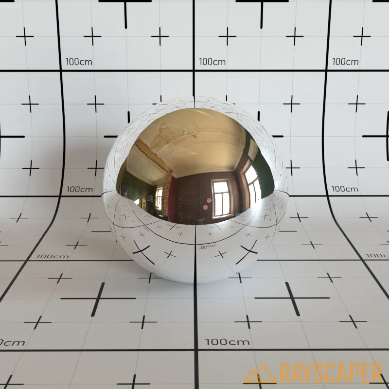
A mirror material reflecting the environment.
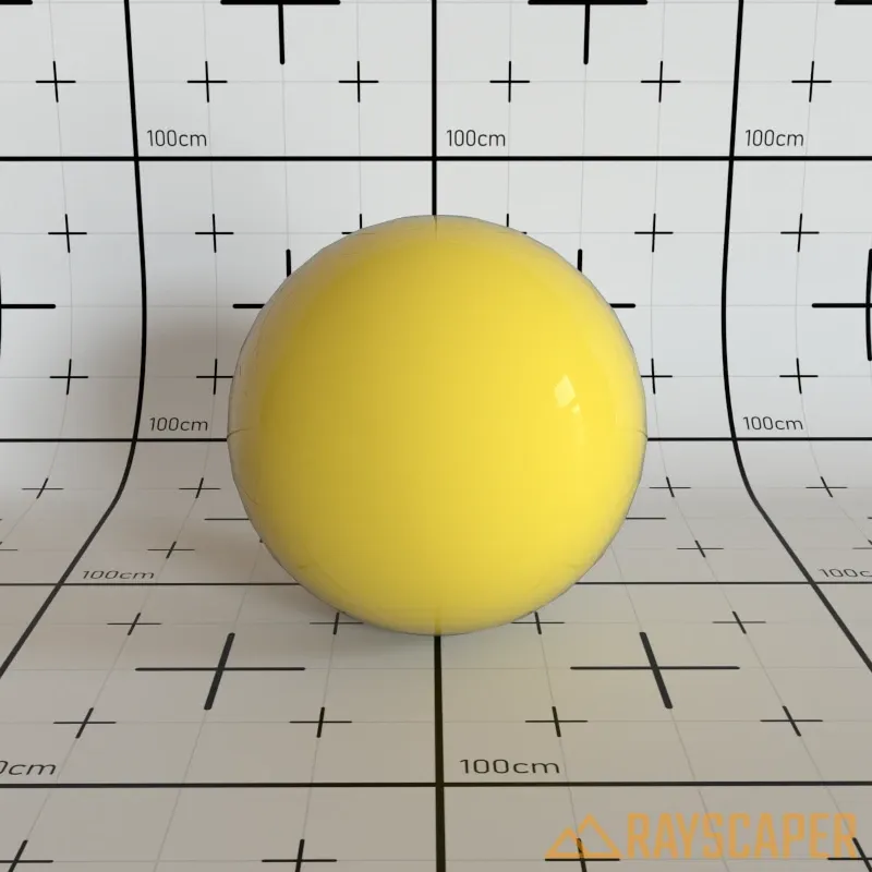
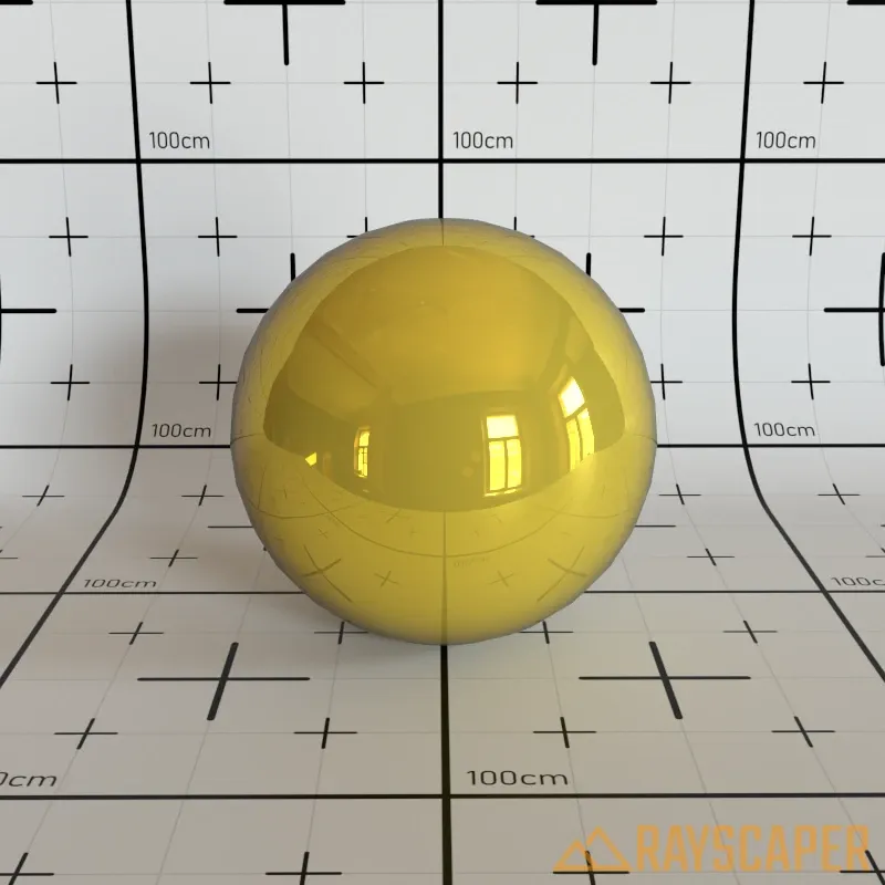
PBR Material
Section titled “PBR Material”Rayscaper’s most versatile material, capable of representing nearly any real-world surface. Based on Physically Based Rendering principles—often called the “principled” or “Disney” material in other applications.
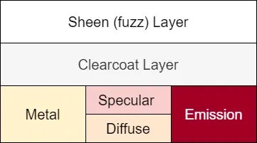
The layered structure of the PBR material showing how different components stack together.
The PBR material works by stacking multiple layers on top of each other. At the base, the Metallic parameter blends between a diffuse layer (for non-metals like plastic or wood) and a metal layer (for metallic surfaces). The Specular reflection sits on top, creating glossy highlights.
You can add Emission to make the material glow. On top of the base, an optional Clearcoat Layer adds a glossy varnish-like coating. At the very top, the Sheen Layer creates a fuzzy edge glow for fabrics like velvet. The Transmission parameter allows light to pass through the material for glass-like effects.
Main Settings
Section titled “Main Settings”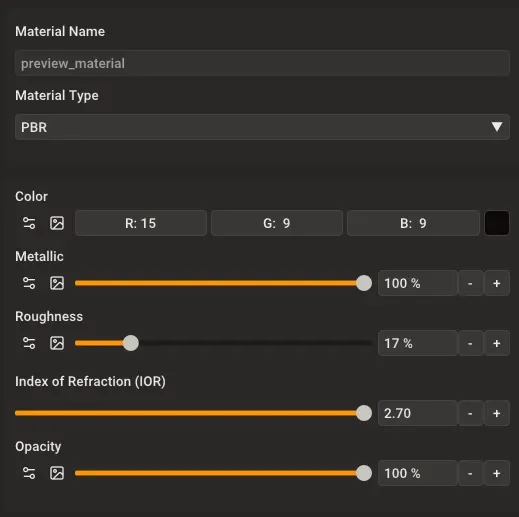
The PBR material main settings panel.
Color: Base color (albedo) of the material. For realistic results, use an image texture showing the surface’s natural color.
Metallic: Blends between non-metal (0%) and metal (100%). At 0%, the material behaves like plastic or stone. At 100%, it behaves like polished metal. Use a metallic map texture for complex materials like worn metal with exposed base material.
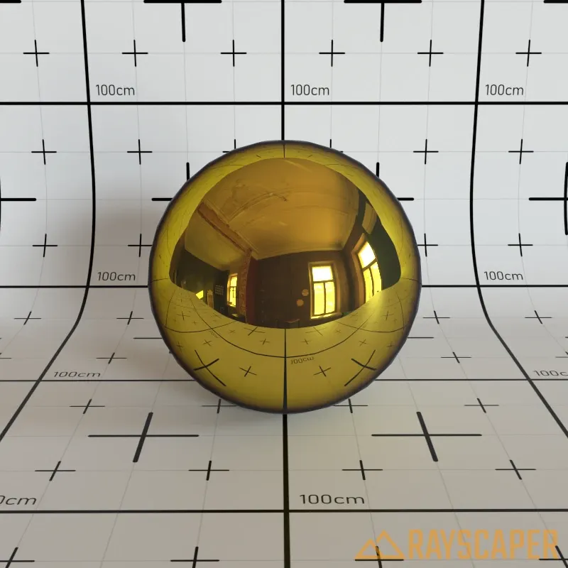
Roughness: Controls surface smoothness. A value of 0% creates mirror-smooth surfaces with sharp reflections, while 100% creates completely rough surfaces with no visible reflections. Use a roughness map texture for realistic variation across the surface.
Index of Refraction (IOR): Controls the strength of reflections, especially at grazing angles. Higher values create stronger reflections. The default value of 1.50 works well for most materials like plastic and glass.


Advanced Settings
Section titled “Advanced Settings”
The PBR material advanced settings panel.
Expand the Advanced Settings section to access additional controls for specialized material effects.
Transmission
Section titled “Transmission”Controls how much light passes through the material. A value of 0% makes the material completely opaque, while 100% makes it fully transmissive like glass. Use this to create glass-like materials or partially transparent surfaces. The Index of Refraction (IOR) setting in the main settings controls how much the background bends and distorts when viewed through the material—higher IOR values create stronger distortion, like looking through thick glass.
Creates edge shimmer for fabric-like materials. This simulates the fuzzy glow seen on velvet, satin, and similar cloth materials with visible fiber highlights at grazing angles.
Strength: A value of 0% disables the effect entirely, while 100% creates strong fabric-like edge glow.
Tint: Tint color applied to the sheen effect. Use white for neutral sheen or a color to tint the edge highlights.
Roughness: Controls the roughness of the sheen effect. Lower values produce sharper, more defined highlights, while higher values create softer, more diffuse edge glow.

Coating
Section titled “Coating”Adds a clear coat layer like varnish or lacquer on top of the base material. Works best over rough base surfaces to create materials like car paint or varnished wood.
Strength: A value of 0% disables the coating, while 100% applies it at full strength.

Roughness: Controls the smoothness of the clear coat layer. A value of 0% produces sharp, glossy highlights, while 100% produces soft, matte highlights.
Specular
Section titled “Specular”Controls the appearance of specular highlights on the material surface.
Tint: Tint color applied to specular highlights. Use white for neutral highlights (physically accurate for most materials) or a color to create tinted reflections.
Anisotropy
Section titled “Anisotropy”Stretches specular highlights in one direction. Use this for brushed metal, hair, satin, or any material with directional surface structure.
Strength: Higher values elongate the highlights along the surface’s tangent direction.

Rotation: Rotates the direction of the anisotropic highlight stretching. By default (0°), highlights stretch horizontally along the surface’s tangent direction. Adjusting this angle lets you align the stretch direction with the grain pattern of your material—for example, rotating 90° creates vertical stretching for wood grain running up and down, or matching the circular brushing pattern on a metal pot lid.
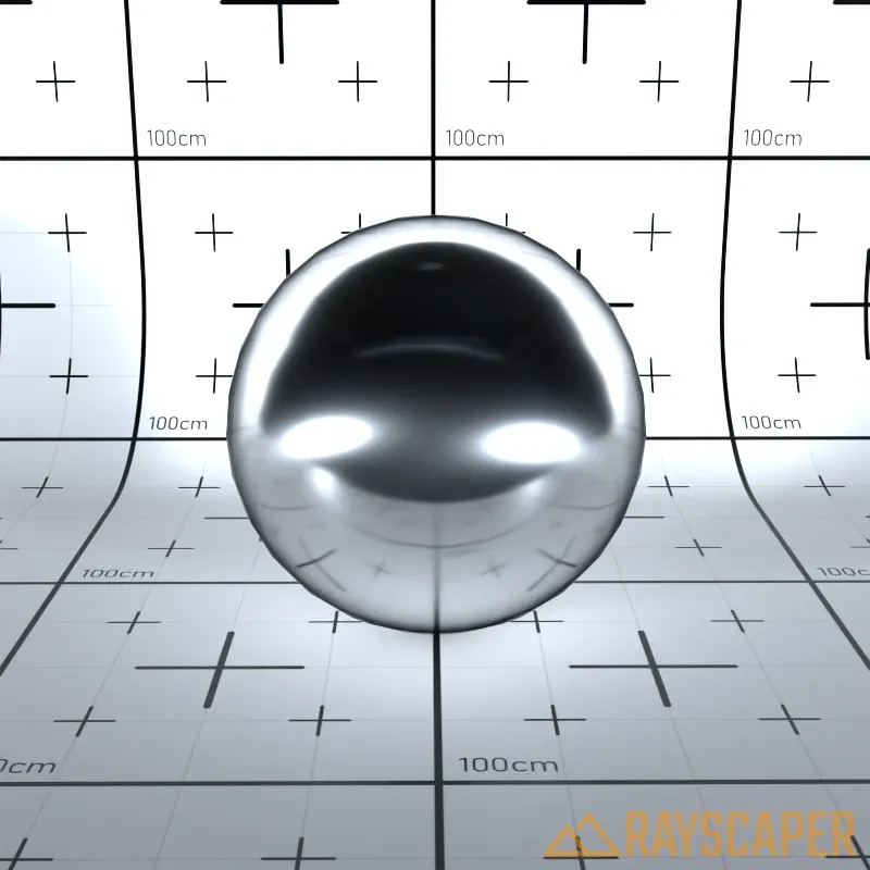
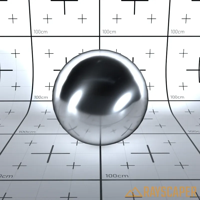
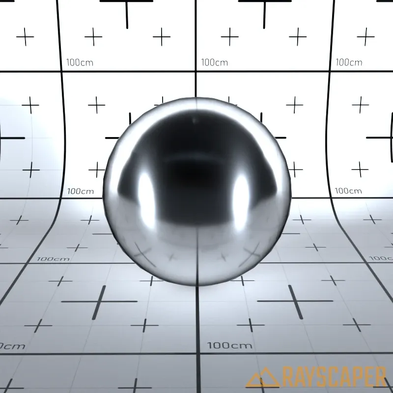
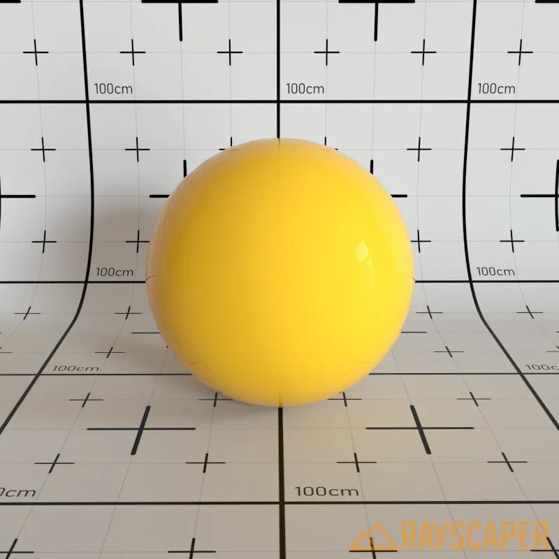
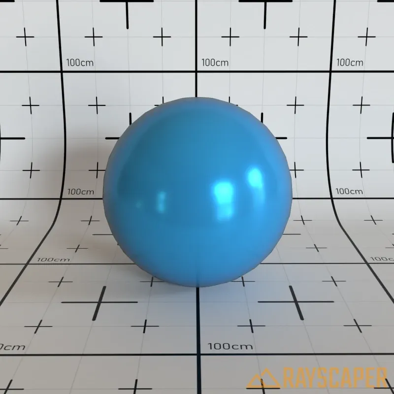
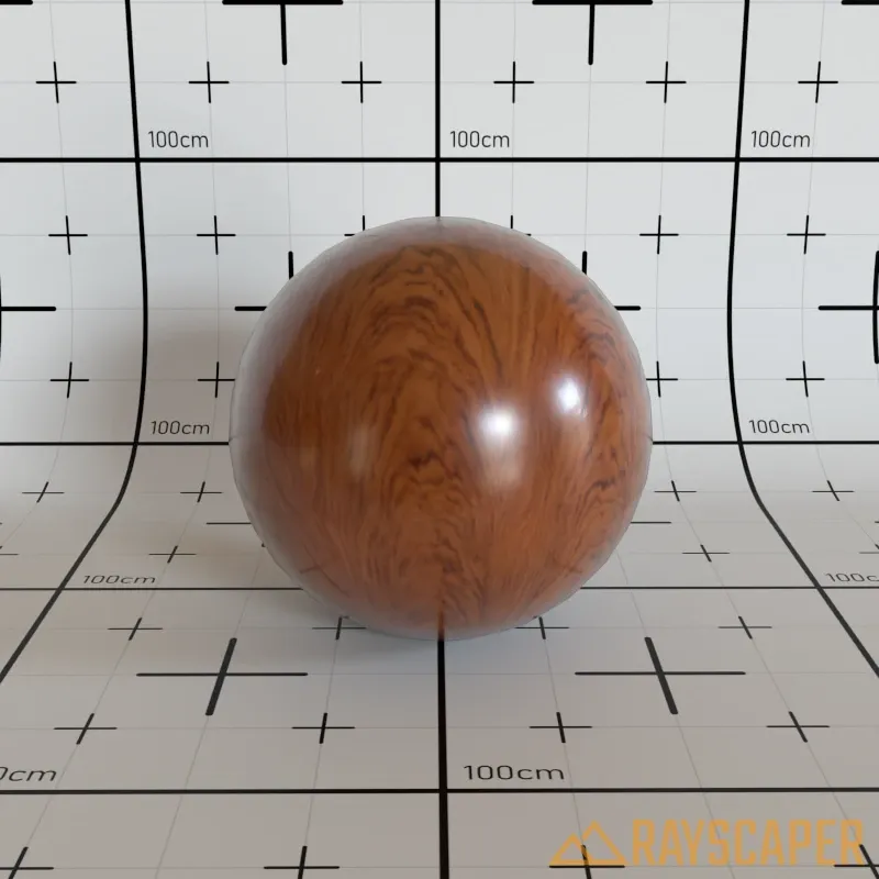
Plastic Material
Section titled “Plastic Material”A diffuse base with a colored glossy layer on top. Unlike Coated Material, the Plastic material allows the specular reflection to have its own independent color. Ideal for plastics, glossy paints, and materials with tinted highlights.
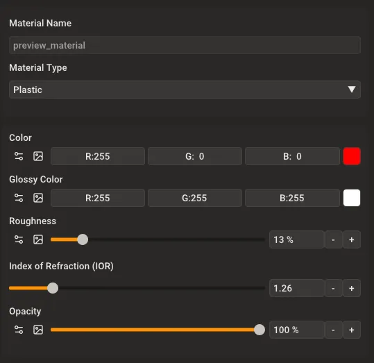
Plastic material settings showing Color, Glossy Color, Roughness, IOR, and Opacity controls.
Color: The base diffuse color of the material. This is the underlying surface color visible in areas without reflections.
Glossy Color: The color of the specular highlights and reflections. This creates tinted reflections, which is characteristic of colored plastics and paints.
Roughness: Controls the sharpness of reflections and highlights. A value of 0% produces sharp, glossy reflections like polished plastic, while higher values create softer, more satin-like appearances.
Index of Refraction (IOR): Controls reflection intensity at different viewing angles. Typical value is around 1.5 for most plastics.
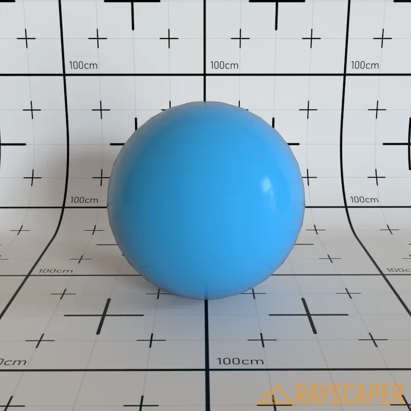
A plastic material with red base color and white glossy highlights.