Lights
Lighting is one of the most important aspects of creating realistic renders. Without proper lighting, even the best materials and geometry will look flat and lifeless. Rayscaper provides four light types to illuminate your scenes:
- Point Light - Radiates light in all directions from a single point (like a light bulb)
- Spotlight - Emits light in a cone shape (like a flashlight or recessed ceiling light)
- Directional Light - Casts parallel rays from one direction (like the sun)
- Area Light - Emits from a flat surface for soft, realistic shadows (like a window or LED panel)
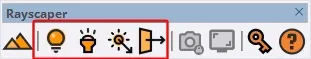
The Rayscaper toolbar in SketchUp with the four light tools: Point Light, Spotlight, Directional Light, and Area Light.
How Light Placement Works
Section titled “How Light Placement Works”Lights in Rayscaper follow a two-step workflow:
-
Place lights using SketchUp tools - Select a light tool from the Rayscaper toolbar and click in your model to position the light. The tool guides you through placing the light at the right location and orientation.
-
Configure lights in Rayscaper - Once placed, adjust the light’s brightness, color, and other settings in the Rayscaper Scene Editor. Changes appear in real-time in the render preview.
This separation keeps the placement process simple and familiar (it works like any other SketchUp tool), while giving you full control over light properties in a dedicated editor.
Light Type Comparison
Section titled “Light Type Comparison”Here’s a comparison of how each light type affects the same scene:
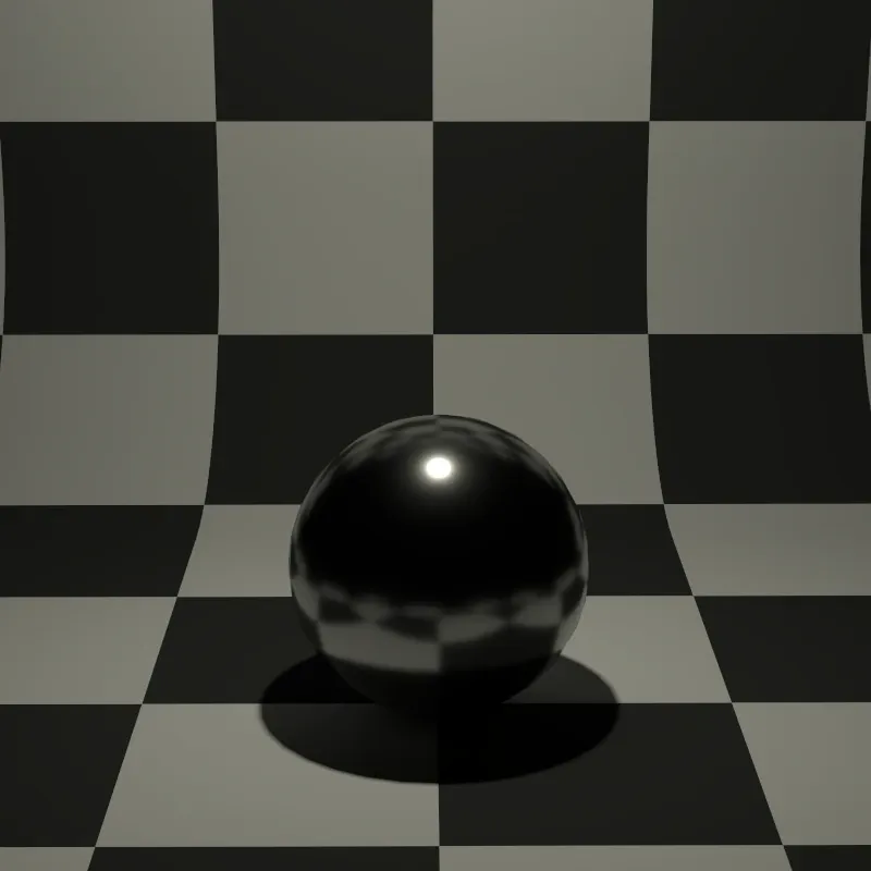
Radiates light equally in all directions, like a bare light bulb.
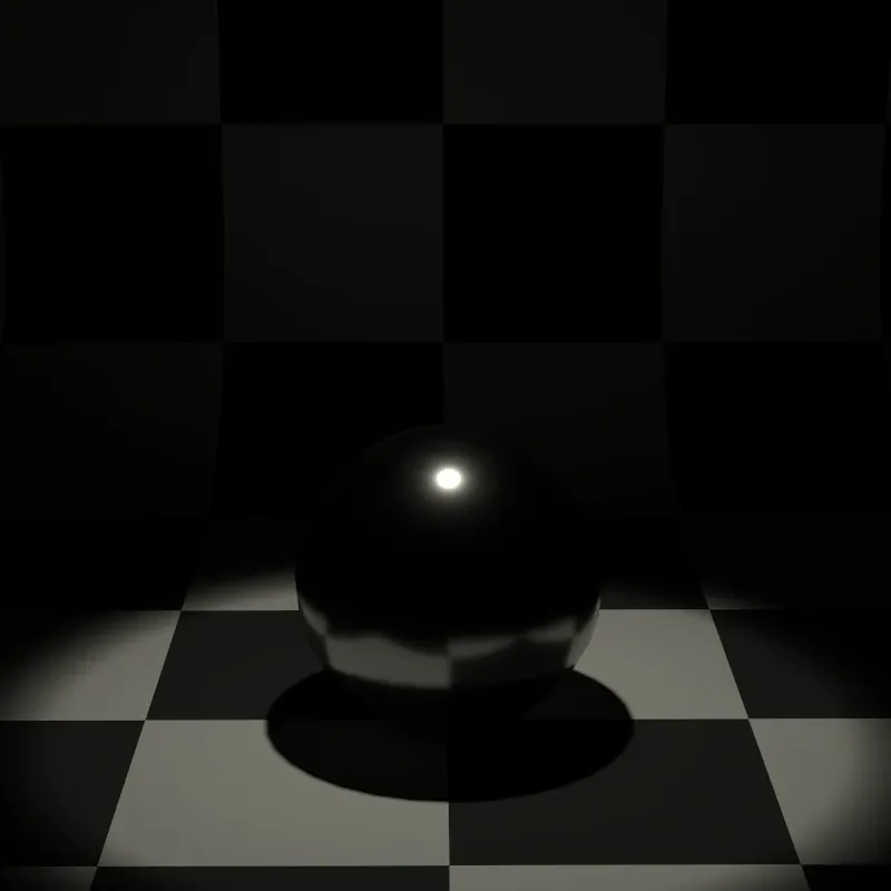
Creates a focused cone of light, perfect for dramatic effects.
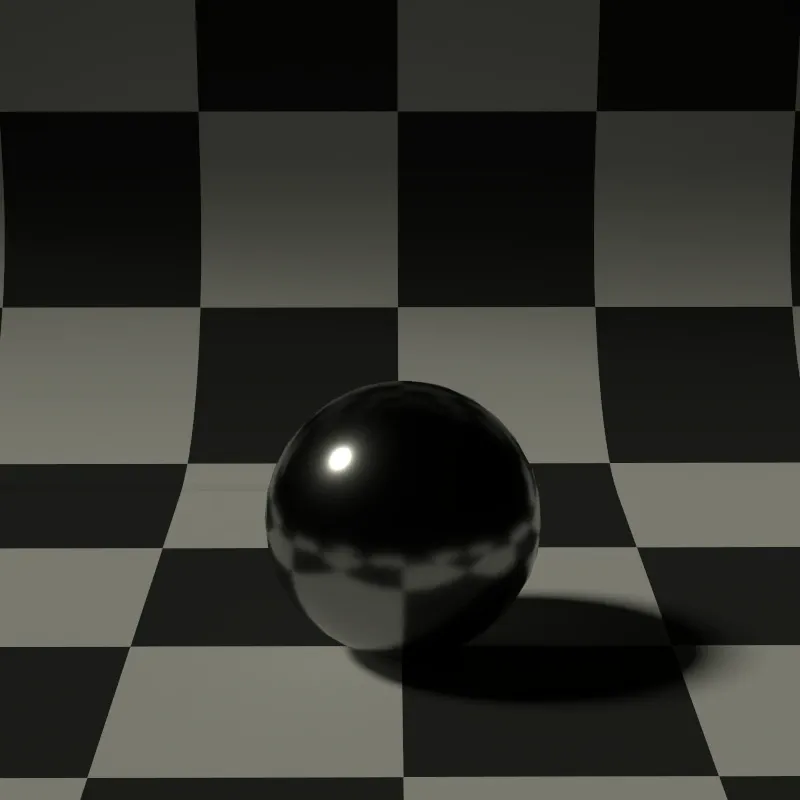
Simulates sunlight with parallel rays coming from a single direction.
Settings Shared by All Lights
Section titled “Settings Shared by All Lights”Before diving into specific light types, let’s cover the settings that every light has in common:
| Setting | Description |
|---|---|
| On | Toggles the light on or off. Useful for quickly comparing scenes with and without a particular light. |
| Mode | Choose how to set the light color: Temperature (realistic) or Color (custom RGB). |
| Intensity | How bright the light is. Higher values = brighter light. |
Understanding Color Temperature
Section titled “Understanding Color Temperature”When Mode is set to Temperature, you control the light color using Kelvin (K) values. This mimics how real-world light sources work:
| Temperature | Color | Real-World Example |
|---|---|---|
| 2700K | Warm orange/yellow | Candle flame, incandescent bulb |
| 4000K | Neutral white | Moonlight, neutral LED |
| 5600K | Daylight white | Midday sun |
| 6500K | Cool white | Overcast sky |
| 10000K | Cool blue | Clear blue sky |
Using Custom Colors
Section titled “Using Custom Colors”When Mode is set to Color, you can pick any RGB color you want. This is useful for:
- Colored accent lighting
- Neon signs or LED strips
- Creative/artistic renders
- Matching specific brand colors
Point Light
Section titled “Point Light”Point lights are the simplest light type. They emit light equally in all directions from a single point in space, like a bare light bulb hanging from the ceiling or a candle flame.
Best uses: General room lighting, lamps without shades, decorative string lights, candles.

Placing a point light: click to set a reference point, then click again to place the light.
How to Place a Point Light
Section titled “How to Place a Point Light”-
Select the Point Light tool (
 ) from the toolbar.
 -
Click anywhere in your scene to set a reference point. This helps SketchUp understand where you want to place the light.
-
Move your mouse to position the light, then click again to confirm.
Point Light Settings
Section titled “Point Light Settings”| Setting | Description |
|---|---|
| Intensity | Brightness of the light, measured in Watts |
| Radius | Size of the light source in meters (affects shadow softness) |
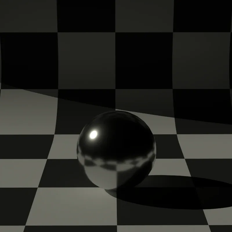
Understanding Radius
Section titled “Understanding Radius”In the real world, light sources have physical size. A tiny LED creates sharp, hard-edged shadows, while a large frosted globe creates soft, gradual shadows. The Radius parameter simulates this:
- Radius = 0: The light is an infinitely small point. Shadows have perfectly sharp edges.
- Radius > 0: The light behaves like a sphere of that radius. Larger values produce softer shadow edges.
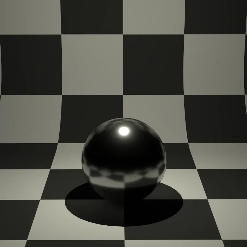
Sharp, hard-edged shadows (infinitely small light source)
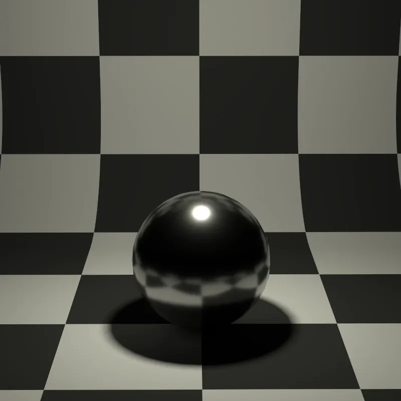
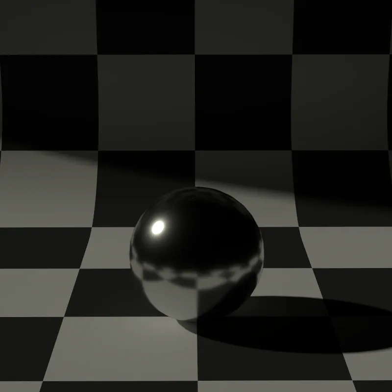
Slightly softened shadow edges
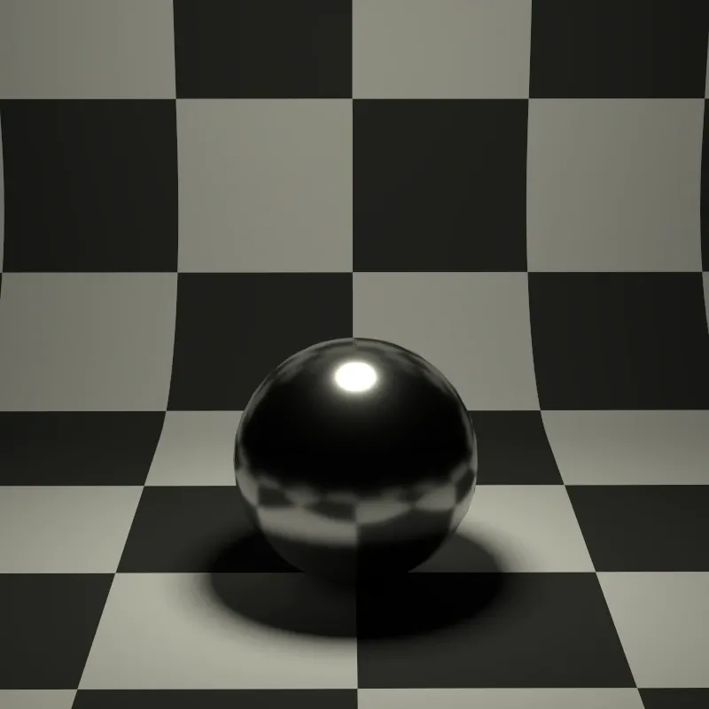
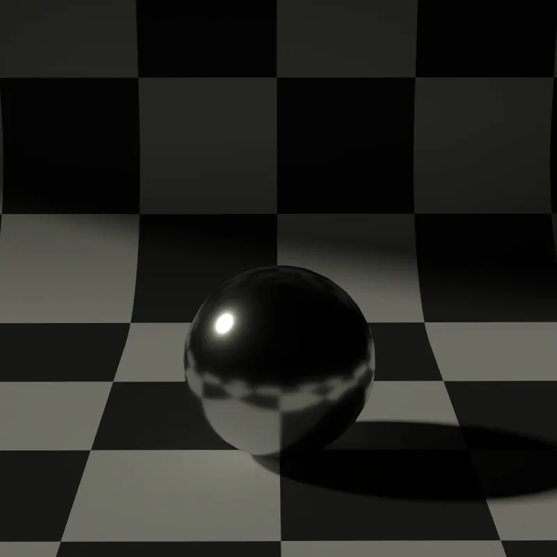
Noticeably soft shadows
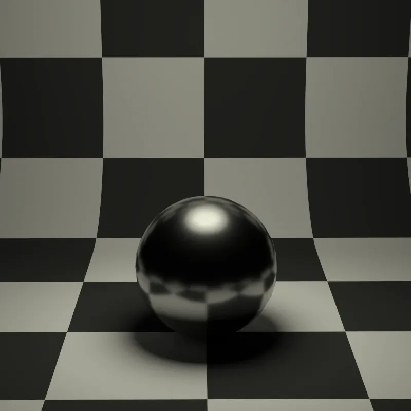
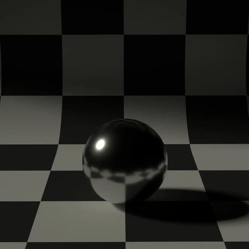
Very soft, diffuse shadows
Spotlight
Section titled “Spotlight”Spotlights emit light in a cone shape, making them perfect for focused, directional lighting. Think of recessed ceiling lights, stage spotlights, flashlights, or car headlights.
Best uses: Recessed downlights, track lighting, accent lighting, stage effects, flashlights.

Placing a spotlight: set a reference point, position the light, then aim it at a target.
How to Place a Spotlight
Section titled “How to Place a Spotlight”-
Select the Spotlight tool (
 ) from the toolbar.
 -
Click to set a reference point.
-
Click again to set the light position.
-
Move your mouse to aim the spotlight, then click to confirm the direction.
Spotlight Settings
Section titled “Spotlight Settings”| Setting | Description |
|---|---|
| Intensity | Brightness of the light, measured in Watts |
| Radius | Shadow softness in meters (same as point lights) |
| Cone Angle | How wide the light cone spreads, in degrees |
| Falloff | How gradually the light fades at the cone edges (0 = hard edge, 1 = soft fade) |
Understanding Cone Angle and Falloff
Section titled “Understanding Cone Angle and Falloff”These two settings work together to control the spotlight’s shape:
-
Cone Angle determines how wide the spotlight beam spreads. A narrow angle (like 10 degrees) creates a tight beam; a wide angle (like 60 degrees) covers a larger area.
-
Falloff controls the transition at the edge of the cone:
- Falloff = 0: Hard cutoff - light stops abruptly at the cone edge (like a theatrical spotlight with a sharp edge)
- Falloff = 1: Gradual fade - light smoothly fades to darkness at the edges (more natural-looking)
- Falloff = 0.3: A balanced blend that works for most scenarios
Directional Light
Section titled “Directional Light”Directional lights cast parallel rays from a single direction, as if the light source were infinitely far away. This is how sunlight and moonlight work in the real world - the source is so distant that all rays are essentially parallel.
Best uses: Sunlight, moonlight, any distant light source.

Placing a directional light: set a reference point, position the icon, then set the light direction.
How to Place a Directional Light
Section titled “How to Place a Directional Light”-
Select the Directional Light tool (
 ) from the toolbar.
 -
Click to set a reference point.
-
Click again to set the light position. This determines where the light icon appears, but doesn’t affect the lighting since directional lights illuminate from infinitely far away.
-
Move your mouse to set the light direction, then click to confirm.
Directional Light Settings
Section titled “Directional Light Settings”| Setting | Description |
|---|---|
| Intensity | Brightness of the light, measured in Watts |
| Angle | Angular diameter in degrees (affects shadow softness) |
Understanding the Angle Parameter
Section titled “Understanding the Angle Parameter”The Angle setting represents the angular diameter of the light source as seen from your scene. This is different from direction - it controls how “big” the sun or moon appears in the sky, which affects shadow softness.
- The real sun has an angular diameter of about 0.53 degrees
- Smaller angles create sharper shadows
- Larger angles create softer, more diffuse shadows
Perfectly sharp shadows (infinitely small sun)
Slightly soft shadows
Noticeably soft shadows (overcast feel)
Very soft, diffuse shadows
SketchUp Sun
Section titled “SketchUp Sun”Instead of manually placing a directional light for sunlight, you can have Rayscaper automatically sync with SketchUp’s built-in shadow system. When enabled, Rayscaper creates a special directional light called SketchUp Sun that follows the sun direction from SketchUp’s Shadows panel.
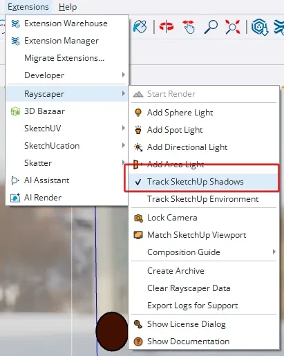
The “Track SketchUp Shadows” option in the Extensions > Rayscaper menu.
To enable SketchUp Sun tracking:
-
Go to Extensions > Rayscaper in SketchUp’s menu.
-
Click Track SketchUp Shadows to enable it (a checkmark appears when active).
Once enabled, a directional light named “SketchUp Sun” appears in Rayscaper’s light list. This light automatically updates its direction whenever you change the time or date in SketchUp’s Shadows panel.
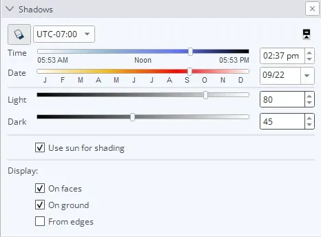
SketchUp’s Shadow Settings panel controls the sun direction for the SketchUp Sun light.
You can adjust the time of day, date, and location in SketchUp’s Shadows panel (Window > Shadows), and the SketchUp Sun light in Rayscaper will update in real-time to match.
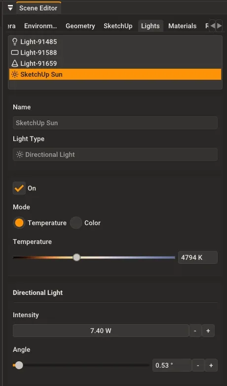
The SketchUp Sun light in Rayscaper’s Scene Editor, showing its settings.
The SketchUp Sun light works like any other directional light - you can adjust its intensity, color temperature, and angle in Rayscaper’s Scene Editor. However, the light direction is controlled by SketchUp’s shadow settings, not manually.
Area Light
Section titled “Area Light”Area lights emit from a flat rectangular or elliptical surface, producing the most realistic soft shadows. Unlike point lights where you artificially increase the radius for softer shadows, area lights are physically larger, so the shadow softness varies naturally with distance - objects close to the light have sharper shadows, while distant objects have softer shadows.
Best uses: Windows (daylight coming through), LED panels, softboxes, TV screens, any large glowing surface.
Placing an area light: define the rectangle size, then set the emission direction.
How to Place an Area Light
Section titled “How to Place an Area Light”-
Select the Area Light tool (
 ) from the toolbar.
 -
Click to set the first corner of the light.
-
Move your mouse and click to set the opposite corner. This defines the size of the light.
-
Move your mouse to set the emission direction (which way the light points), then click to confirm.
Area Light Settings
Section titled “Area Light Settings”| Setting | Description |
|---|---|
| Intensity | Brightness of the light, measured in Watts |
| Normalize | Adjusts brightness based on size |
| Shape | Rectangle or Ellipse |
| Size | Dimensions in meters (read-only, controlled by SketchUp component scale) |
| Spread | How widely the light disperses, in degrees |
Understanding Normalize
Section titled “Understanding Normalize”The Normalize setting controls how brightness relates to the light’s size:
-
Normalize ON: The light maintains consistent brightness per unit area. If you make the light twice as big, each square meter emits the same amount of light, so the total light output increases. This is physically accurate - a bigger light panel should emit more total light.
-
Normalize OFF: The total light output stays constant regardless of size. Making the light bigger spreads the same amount of light over a larger area, so each point appears dimmer.
Understanding Spread
Section titled “Understanding Spread”The Spread parameter controls the emission angle - how widely the light disperses from the surface:
- Spread = 0 degrees: Light only emits straight out, perpendicular to the surface (like a laser grid)
- Spread = 90 degrees: Light emits in a hemisphere (like a typical diffuse surface)
- Spread = 180 degrees: Light emits in all directions from the surface (wraps around edges)
For most scenarios, a low spread value (10-30 degrees) works well for directional lights like panels, while higher values (90+ degrees) work better for simulating windows or glowing surfaces.
Selecting Lights
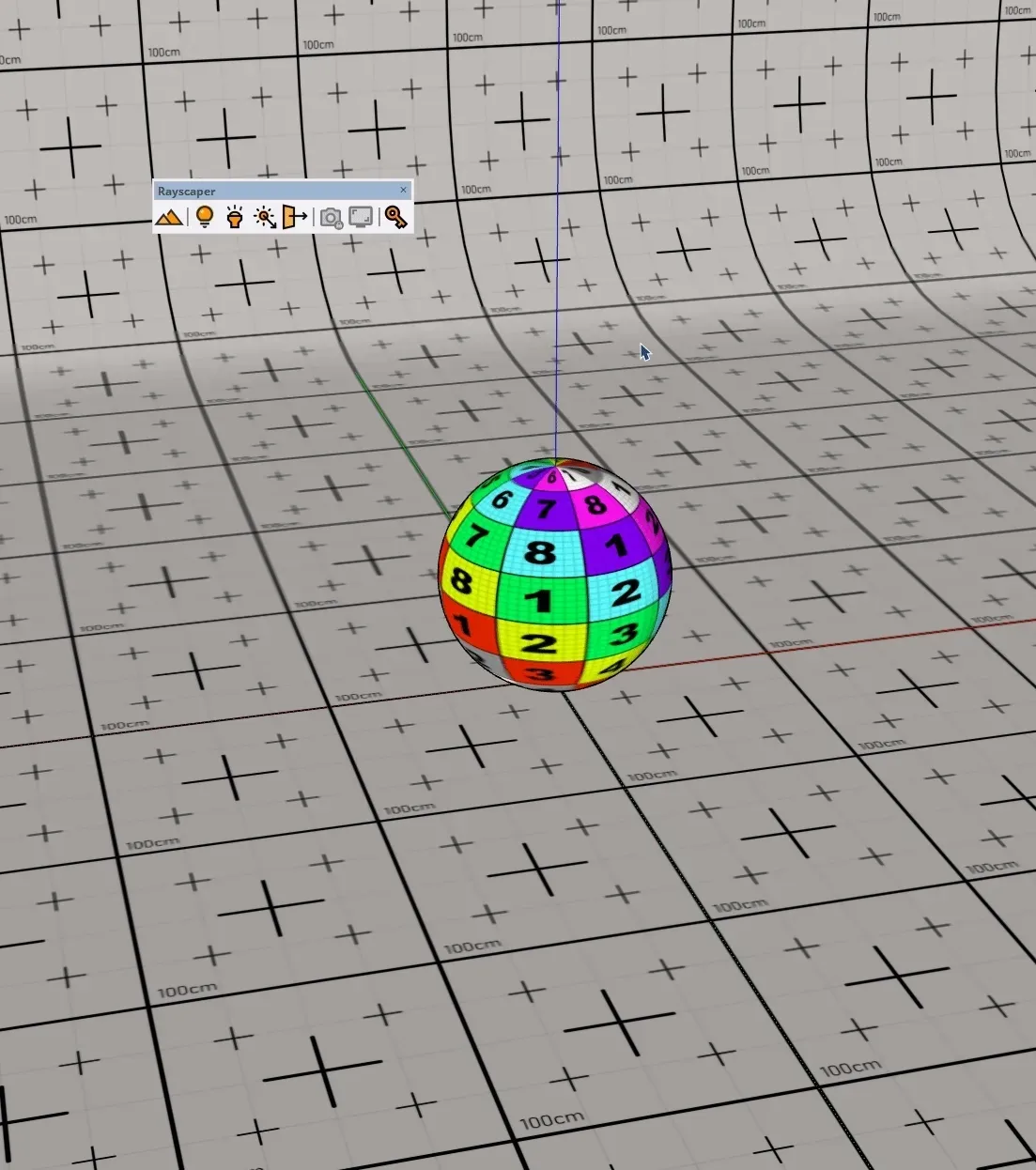
Section titled “Selecting Lights”Using Light Overlays
Section titled “Using Light Overlays”When light overlays are enabled, clickable icons appear in the viewport at each light’s position. This makes it easy to select lights directly in your scene without hunting through the light list.
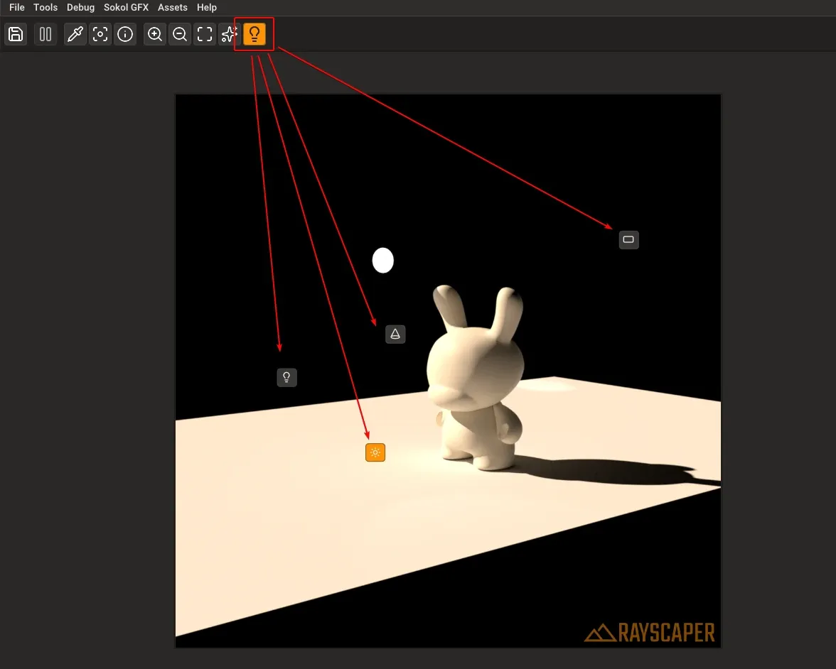
Light overlay icons in the Rayscaper viewport. Click any icon to select that light.
Each light type has a distinct icon:
- Point lights show a lightbulb icon
- Spotlights show a cone icon
- Directional lights show a sun icon
- Area lights show a rectangle icon
To toggle light overlays, click the light overlay button in the viewport toolbar (the lightbulb icon highlighted in the image above).
Click any light icon in the viewport to select it. Hold Ctrl (Windows) or Cmd (Mac) while clicking to add or remove lights from your selection. Selected lights are highlighted in orange, and disabled lights appear dimmed.
Editing Multiple Lights
Section titled “Editing Multiple Lights”You can select and edit multiple lights at once in the Rayscaper scene editor. Hold Ctrl (Windows) or Cmd (Mac) while clicking lights in the list or viewport to select multiple. Any changes you make will apply to all selected lights.
Quick Reference
Section titled “Quick Reference”| Light Type | Best For |
|---|---|
| Point Light | Lamps, bulbs, candles |
| Spotlight | Recessed lights, stage lighting |
| Directional Light | Sun, moon |
| Area Light | Windows, panels, softboxes |